Wafer cleaning device

A technology for cleaning devices and wafers, applied in cleaning methods and tools, cleaning methods using liquids, static electricity, etc., can solve problems such as wafer yield decline, poor arcing, etc., to eliminate static charges, ensure quality, and increase revenue rate effect

Pending Publication Date: 2021-04-20
XIA TAI XIN SEMICON QING DAO LTD
View PDF10 Cites 3 Cited by
  • Summary
  • Abstract
  • Description
  • Claims
  • Application Information

AI Technical Summary

Problems solved by technology

[0002] During the cleaning process of the wafer, when the spin chamber of the cleaning equipment is being processed, the spin chuck (Spin Chuck) rotates or the fluid flowing in the Teflon (Teflon) pipe will generate static electricity due to friction, but this static electricity will make the wafer The surface of the circle is covered with particles, which is prone to poor arcing during the wafer patterning process, result

Method used


Image

  • Wafer cleaning device
  • Wafer cleaning device
  • Wafer cleaning device

Examples


Embodiment Construction

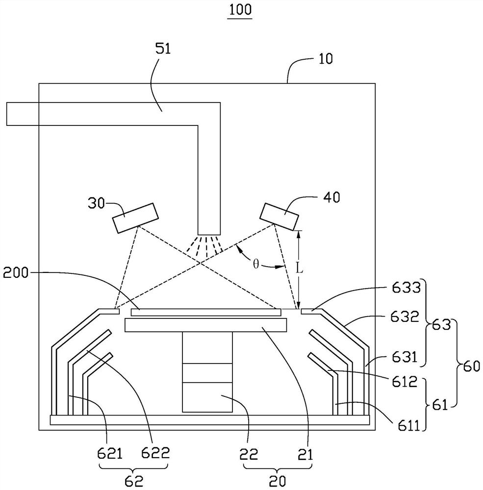
[0055] see figure 1 , the wafer cleaning device 100 provided in the first embodiment of the present invention can eliminate the static electricity generated by the wafer 200 during the cleaning process. The wafer cleaning device 100 includes a spin chamber 10, a spin assembly 20, an electrostatic sensor 30, a soft X-ray ionizer 40, a cleaning fluid supply assembly (not shown) and a cleaning fluid recovery assembly 60, wherein the rotation assembly 20, the electrostatic The sensor 30 , the soft X-ray ionizer 40 and the cleaning fluid recovery assembly 60 are all disposed in the spin chamber 10 .

[0056] The rotating assembly 20 includes a rotating table 21 and a driving assembly 22 , the rotating table 21 is disposed on the driving assembly 22 and rotates under the driving action of the driving assembly 22 . The turntable 21 is used to carry the wafer 200 . Further, the turntable 21 is provided with a suction cup (not shown) for holding the wafer 200 so that the wafer 200 ro...


PUM

PropertyMeasurementUnit
Angleaaaaaaaaaa

Abstract

The invention discloses a wafer cleaning device. The wafer cleaning device comprises a rotary chamber, a rotating assembly, an electric sensor and a soft X-ray ionizer; the rotating assembly is arranged in the rotating chamber, the rotating assembly comprises a rotating table, and a suction cup is arranged on the rotating table and used for sucking a wafer so that the wafer can rotate along with rotation of the rotating table; the electrostatic sensor is used for sensing whether electrostatic charges exist on the wafer or not; and the soft X-ray ionizer is arranged above the wafer, and when the electrostatic sensor senses that the electrostatic charge exists on the wafer, the soft X-ray ionizer irradiates soft X-rays to the wafer to ionize air in the rotating chamber so as to eliminate the electrostatic charge on the wafer. By the mode, static electricity generated on the wafer can be effectively eliminated.

Description

technical field [0001] The invention relates to a wafer cleaning device. Background technique [0002] During the cleaning process of the wafer, when the spin chamber of the cleaning equipment is being processed, the spin chuck (Spin Chuck) rotates or the fluid flowing in the Teflon (Teflon) pipe will generate static electricity due to friction, but this static electricity will make the wafer The surface of the circle is covered with particles, which is prone to poor arcing during the wafer patterning process, which in turn leads to a decrease in the yield of the wafer. [0003] At present, static electricity is usually eliminated in the following ways. One is to install the wafer holder made of carbon material on the spin chuck and ground it, and the other is to spray carbon dioxide fluid on the wafer before processing using spray technology. However, in In practical application, it is found that the above-mentioned method does not solve the above-mentioned problem. Cont...

Claims


Application Information

Patent Timeline
IPC IPC(8): B08B3/02B08B13/00H05F3/06
Inventor 朴英植
Owner XIA TAI XIN SEMICON QING DAO LTD
Why Eureka
Try Eureka