Forward and reverse scouring dredging method for diversion canal of hydropower station and diversion canal structure

A diversion canal, forward and reverse technology, applied in the field of hydropower station diversion canal forward and reverse scouring and dredging methods and diversion canal structure, can solve problems such as time-consuming, laborious, insufficient diversion flow for power generation, high cost, etc.

Active Publication Date: 2021-04-20
CHINA INST OF WATER RESOURCES & HYDROPOWER RES +1
View PDF4 Cites 0 Cited by
  • Summary
  • Abstract
  • Description
  • Claims
  • Application Information

AI Technical Summary

Problems solved by technology

It is difficult for a hydropower station with a small storage capacity to reduce the sediment content entering the power generation system by sedimentation in the reservoir. A large amount of sediment easily enters the aqueduct with the water flow, causing siltation in the aqueduct, thereby reducing the flow capacity of the aqueduct, which in turn leads to diversion for power generation. Insufficient; the siltation of the diversion channel has a great impact on the power generation efficiency, and is one of the concerns in the operation of small and medium-sized hydropower stations
[0003] At present, the sediment deposited in the diversion channel is generally removed by mechanical dredging, but this dredging method is time-consuming, laborious and expensive

Method used


Image

  • Forward and reverse scouring dredging method for diversion canal of hydropower station and diversion canal structure
  • Forward and reverse scouring dredging method for diversion canal of hydropower station and diversion canal structure
  • Forward and reverse scouring dredging method for diversion canal of hydropower station and diversion canal structure

Examples


Embodiment Construction

[0038] The present invention will be further described below in conjunction with accompanying drawing.

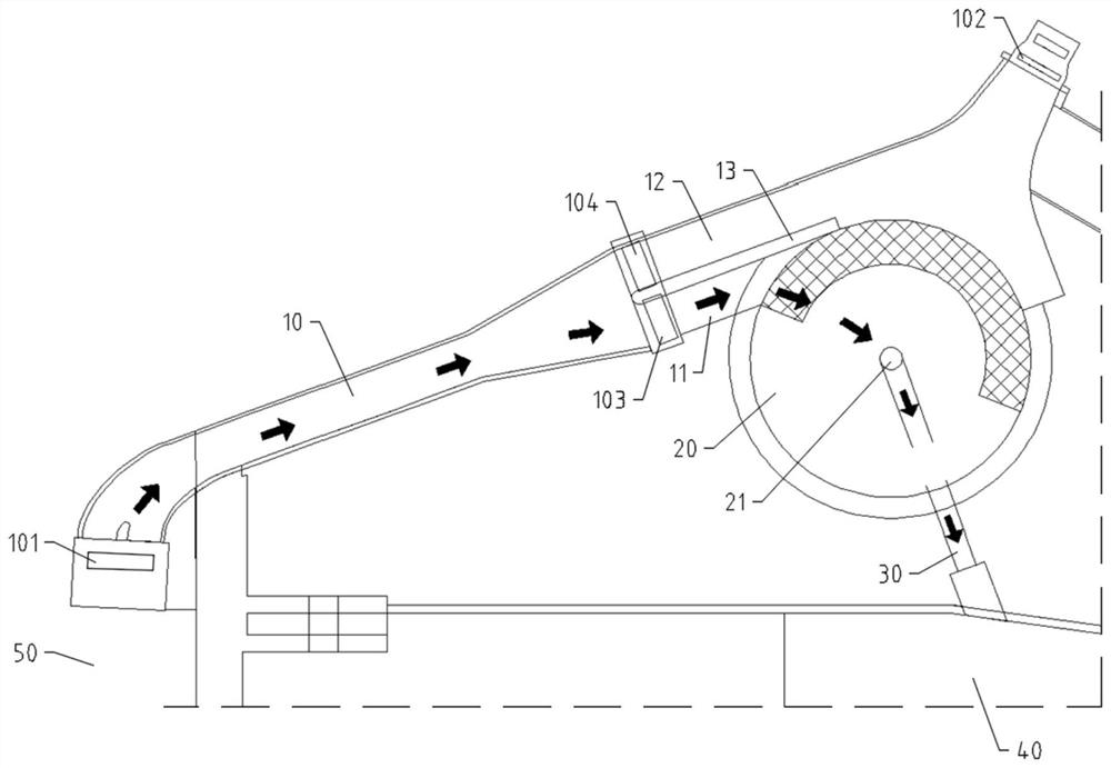
[0039] The invention provides a hydropower station diversion canal forward and reverse scouring dredging method, comprising the following steps:

[0040] Step S10, determine the gradation of the silt in the diversion channel 10 by screening with a vibrating sieve or measuring with a laser particle size analyzer;

[0041] Specifically, to wash away the sediment by water flow, it is first necessary to determine the gradation of the sediment, that is, the distribution of sediment particles of different particle sizes in the sediment. The determination of gradation can be carried out by selecting a vibrating sieve with a certain mesh number to sieve the silt and sediment, or by using a laser particle size analyzer for direct measurement.

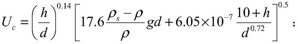
[0042] Step S20, according to the gradation curve of the silt and sand, using the silt particle size corresponding to d90 on the gradation ...


PUM


Abstract

The invention provides a forward and reverse scouring dredging method for a diversion canal of a hydropower station and a diversion canal structure. The method comprises the steps that S10, the gradation of deposited silt in the diversion canal is determined; S20, the representative particle size and the corresponding starting flow velocity of the deposited silt are determined according to a gradation curve of the deposited silt; S30, the starting flow needed for removing the deposited silt through water flow scouring is determined according to the Manning formula; S40, the target opening degree of a gate of the diversion canal is determined according to the starting flow and a flow discharge capacity curve of the diversion canal; and S50, according to the target opening degree, a diversion gate at the head of the diversion canal is opened firstly for forward scouring, and then a power generation diversion tunnel gate at the tail of the diversion canal is opened for reverse scouring. Based on the technical scheme, forward and reverse scouring dredging is achieved through hydraulic power, a large amount of deposited silt is removed with low cost, and the power generation loss and the dredging cost caused by silt deposition of the hydropower station are reduced.

Description

technical field [0001] The invention relates to the technical field of dredging of hydropower stations, in particular to a dredging method for forward and reverse scouring of a diversion channel of a hydropower station and a structure of the diversion channel. Background technique [0002] In the field of hydropower stations, hydropower stations with small storage capacity generally use lateral water diversion to generate power. The water flow in the river channel enters the water diversion tunnel of the hydropower station through the diversion channel, and then passes through the machine to generate electricity. Therefore, the diversion channel is an important structure of the hydropower station, and its flow capacity is one of the key links affecting the power generation efficiency of the hydropower station. It is difficult for a hydropower station with a small storage capacity to reduce the sediment content entering the power generation system by sedimentation in the rese...

Claims


Application Information

Patent Timeline
IPC IPC(8): E02B3/02E02B9/02E02B5/08E02B8/02
CPCY02E10/20Y02A10/00
Inventor 盛玉明王党伟张国来邓安军俞祥荣郭庆超白存忠史红玲晏洪伟吉祖稳金勇陆琴
Owner CHINA INST OF WATER RESOURCES & HYDROPOWER RES
Why Eureka
Try Eureka