
Anti-floating anchor rod construction structure

An anti-floating anchor rod and anchor rod technology, which can be used in infrastructure engineering, sheet pile walls, protection devices, etc., can solve problems such as large buoyancy, increased pressure, and increased structure.

Pending Publication Date: 2021-04-20
BEIJING URBAN CONSTR GROUP
View PDF0 Cites 1 Cited by
  • Summary
  • Abstract
  • Description
  • Claims
  • Application Information

AI Technical Summary

Problems solved by technology

The above commonly used methods have their own disadvantages and limitations: increasing the pressure weight usually increases the thickness of the structure, or increases the pressure weight inside, which is uneconomical in most cases; using uplift piles or anchors is It is realized by using its frictional resistance or the anchoring force formed by embedding rock formations, which requires the presence of rock formations on the shallow surface, and has great limitations for areas with poor shallow soil quality.
[0004] However, quite a few coastal cities in my country belong to soft soil areas. There are basically no rock formations within 50 meters of the surface, and the groundwater level is relatively high. Generally, groundwater appears at 0.5 to 1.5 meters above the surface. The buoyancy is relatively large, and special anti-floating designs must be carried out.
[0005] At present, the anti-floating anchor construction adopts the traditional construction technology, and the anti-floating anchor reinforcement is lowered after the hole is formed. However, the traditional anti-floating anchor structure has low strength and poor anti-floating performance, and is not suitable for complex construction environments.

Method used


Image

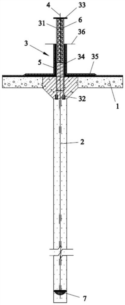
  • Anti-floating anchor rod construction structure
  • Anti-floating anchor rod construction structure

Examples


Embodiment Construction

[0023] The following will clearly and completely describe the technical solutions in the embodiments of the present invention with reference to the accompanying drawings in the embodiments of the present invention. Obviously, the described embodiments are only some, not all, embodiments of the present invention. Based on the embodiments of the present invention, all other embodiments obtained by persons of ordinary skill in the art without making creative efforts belong to the protection scope of the present invention.

[0024] It should be noted that all directional indications (such as up, down, left, right, front, back...) in the embodiments of the present invention are only used to explain the relationship between the components in a certain posture (as shown in the accompanying drawings). Relative positional relationship, movement conditions, etc., if the specific posture changes, the directional indication will also change accordingly.

[0025] In addition, in the presen...


PUM

PropertyMeasurementUnit
Thicknessaaaaaaaaaa
Lengthaaaaaaaaaa
Thicknessaaaaaaaaaa

Abstract

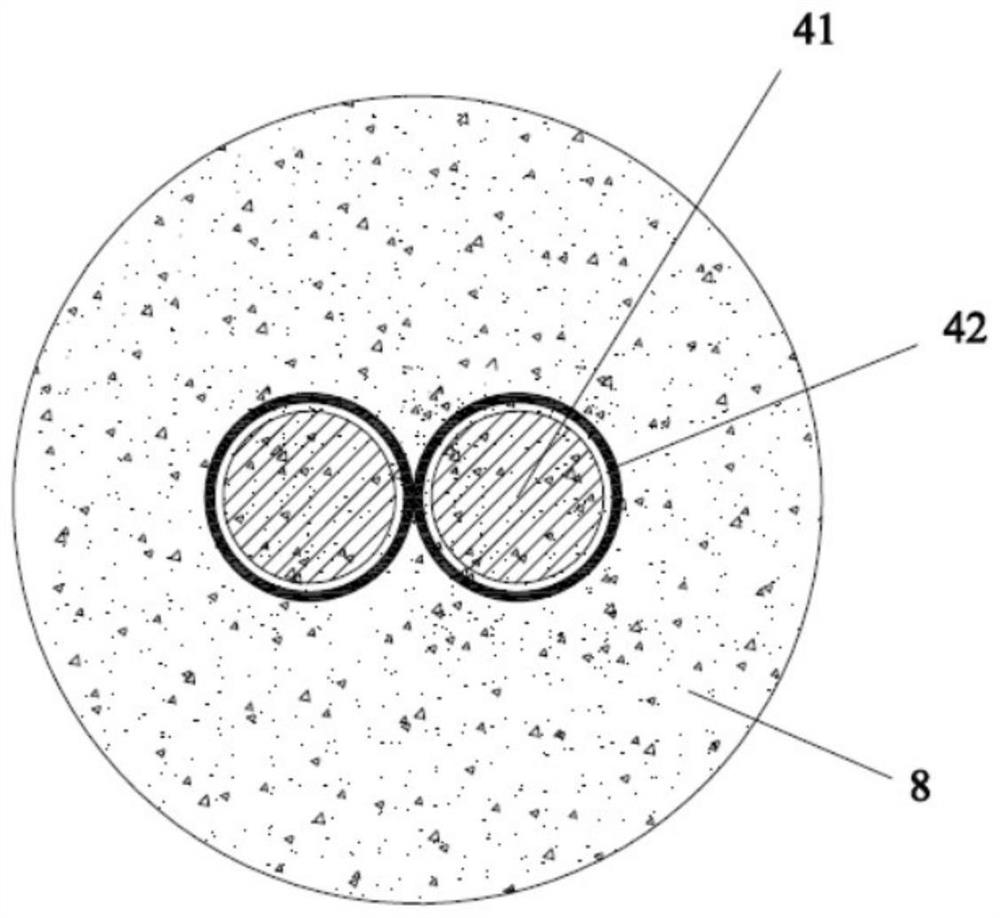
The invention discloses an anti-floating anchor rod construction structure. The anti-floating anchor rod construction structure comprises a cushion layer, an anchor rod part, an anchor rod end part arranged at the top end of the anchor rod part, and a sleeve type anchorage device embedded in the anchor rod part and the anchor rod end part, wherein the anchor rod end part comprises a steel pipe, a rubber pad, an anchor cushion plate, a sealant, a waterproof coiled material and a water stop steel ring plate; the bottom of the steel pipe is embedded in the cushion layer; the rubber pad is mounted at the bottom end of the steel pipe, and butts against the top end of the anchor rod part; the anchor cushion plate is mounted at the top end of the steel pipe; the top end of the sleeve type anchorage device is fixedly arranged on the anchor cushion plate; the sealant wraps the steel pipe, and at least partially extends onto the cushion layer; the waterproof coiled material wraps the sealant, and at least partially extends onto the cushion layer; the water stop steel ring plate sleeves the steel pipe; and a non-cured layer and a micro-expansion waterproof mortar layer are filled in the steel pipe. The anti-floating anchor rod construction structure has the beneficial effects of high structural strength, capability of being applied to various complex construction environments and excellent anti-floating performance.

Description

【Technical field】 [0001] The invention relates to the technical field of construction engineering underground structures, in particular to an anti-floating anchor construction structure. 【Background technique】 [0002] For underground structural projects in areas with high groundwater levels, such as tunnels, basements, underground or semi-underground pools, etc., when the self-weight of the structure is not enough to resist the buoyancy of the groundwater, the structure must be specially designed for anti-floating. [0003] There are several types of anti-floating measures for the general structure itself: ① Increase the pressure to resist buoyancy. ② Use uplift piles to resist buoyancy. ③Anchor with bolts to resist buoyancy. The above commonly used methods have their own disadvantages and limitations: increasing the pressure weight usually increases the thickness of the structure, or increases the pressure weight inside, which is uneconomical in most cases; using uplift ...

Claims


Application Information

Patent Timeline
IPC IPC(8): E02D5/74E02D31/12
Inventor 许宁王自伟冀智马伟国周雷蕾丛龙杰庞少波王鹏骁田强李志新
Owner BEIJING URBAN CONSTR GROUP
Learn More