Novel air heater system arrangement method

A system layout and air heater technology, applied in the field of air heaters, can solve the problems of water heater tube bundles, abnormal noise and vibration of equipment, damage to fan blades, etc., so as to reduce maintenance difficulty, ensure stability, and improve stability. Effect

Pending Publication Date: 2021-04-20
HUANENG POWER INT INC
View PDF0 Cites 0 Cited by
  • Summary
  • Abstract
  • Description
  • Claims
  • Application Information

AI Technical Summary

Problems solved by technology

[0005] For this reason, the embodiment of the present invention provides a new type of heater system layout method to solve the problems in the prior art due to the large air volume and wind speed of the blower and the large heat exchange area of ​​the heater due to the initial stage of the heater being put into operation. , but in order to avoid the vibration of the pipes and equipment at the initial stage of the heater’s operation, the steam supply control valve is gradually opened to adjust the steam supply, which leads to a small amount of steam passing into the heater body but quickly condenses into water. When the ambient wind When the temperature is below zero or lower, it may cause water to accumulate inside the heater tube bundle and slowly freeze, resulting in poor heat transfer effect, poor water drainage, and abnormal noise and vibration of the equipment. Once the heat exchange tube bundle leaks, the accumulated leakage Water or ice cubes will enter the inside of the fan along with the air duct and cause damage to the fan blades

Method used


Image

  • Novel air heater system arrangement method
  • Novel air heater system arrangement method
  • Novel air heater system arrangement method

Examples


Embodiment Construction

[0031] The implementation mode of the present invention is illustrated by specific specific examples below, and those who are familiar with this technology can easily understand other advantages and effects of the present invention from the contents disclosed in this description. Obviously, the described embodiments are a part of the present invention. , but not all examples. Based on the embodiments of the present invention, all other embodiments obtained by persons of ordinary skill in the art without making creative efforts belong to the protection scope of the present invention.

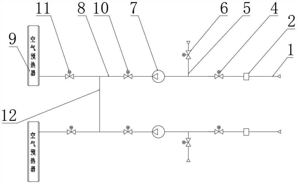
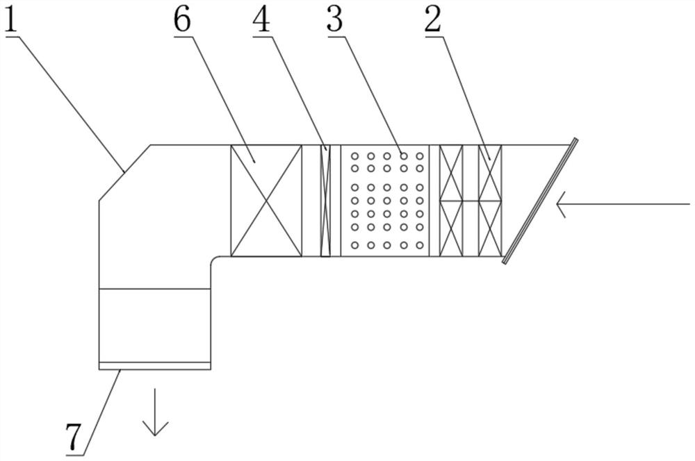
[0032] Refer to the attached Figure 1-7 The layout method of a new type of air heater system shown includes an air inlet pipe 1, a heater body 2 is installed on one side of the inner wall of the air inlet pipe 1, and the input end of the air heater body 2 and the output end of the external power supply are electrically connected. Connection, a muffler 3 is installed on the inner wall side of th...


PUM


Abstract

The invention discloses a novel air heater system arrangement method, and belongs to the technical field of air heaters. The novel air heater system arrangement method comprises an air inlet pipe, an air heater body is arranged on one side of the inner wall of the air inlet pipe, a silencer is arranged on one side, close to the air heater body, of the inner wall of the air inlet pipe, and a main path electric windshield door is arranged on one side, close to the silencer, of the outer surface of the air inlet pipe. A bypass air pipe is installed on the side, close to the main path electric windshield door, of the outer surface of the air inlet pipe, a bypass electric windshield door is installed on one side of the inner wall of the bypass air pipe, and one end of the air inlet pipe is connected with an air feeder. The novel air heater system arrangement method is simple and reasonable in structural design, through cooperative use of the main electric air windshield door, the bypass air pipe and the bypass electric windshield door, the phenomenon that the air heater body is put into use under the condition that quenching does not occur can be avoided, and the use stability of the air heater body can be guaranteed; and the phenomenon that equipment is damaged at an initial stage of air heater body input is avoided.

Description

technical field [0001] The invention relates to the technical field of air heaters, in particular to a novel air heater system arrangement method. Background technique [0002] The existing boiler factory produces 600MW ultra-supercritical unit boilers. The heater is used to heat the primary and secondary air, which is used to increase the temperature of the primary and secondary air and prevent low-temperature corrosion of the air preheater. Each boiler is installed separately Two primary air and secondary air heaters. The heat exchange tubes of the heaters are spiral finned tubes and arranged horizontally. The heaters are arranged in two groups before and after in the inlet air duct of the blower. The heating medium of the heaters is the boiler low-pressure auxiliary Steam supply, temperature 240°C, pressure 0.6Mpa, is sent into the heater body through the steam supply manual door, steam supply regulating door and related pipelines, and a flange is designed on the drain pi...

Claims


Application Information

Patent Timeline
Patent Type & Authority Applications(China)
IPC IPC(8): F23L15/00F28B9/08
CPCY02E20/34
Inventor 孟祥生裴福玲刘文峰孙永军冯鑫刘光旭赵久特王德琦段克迪
Owner HUANENG POWER INT INC
Why Eureka
Try Eureka