Method and device for suppressing distance ambiguity based on antenna pattern synthesis

A technology of antenna pattern and distance ambiguity, which is used in measurement devices, reflection/re-radiation of radio waves, radio wave measurement systems, etc.

Pending Publication Date: 2021-04-20
AEROSPACE INFORMATION RES INST CAS
View PDF0 Cites 5 Cited by
  • Summary
  • Abstract
  • Description
  • Claims
  • Application Information

AI Technical Summary

Problems solved by technology

[0004] The criteria for judging the performance of this type of range ambiguity suppression method are the amount of comput

Method used


Image

  • Method and device for suppressing distance ambiguity based on antenna pattern synthesis
  • Method and device for suppressing distance ambiguity based on antenna pattern synthesis
  • Method and device for suppressing distance ambiguity based on antenna pattern synthesis

Examples


Embodiment 1

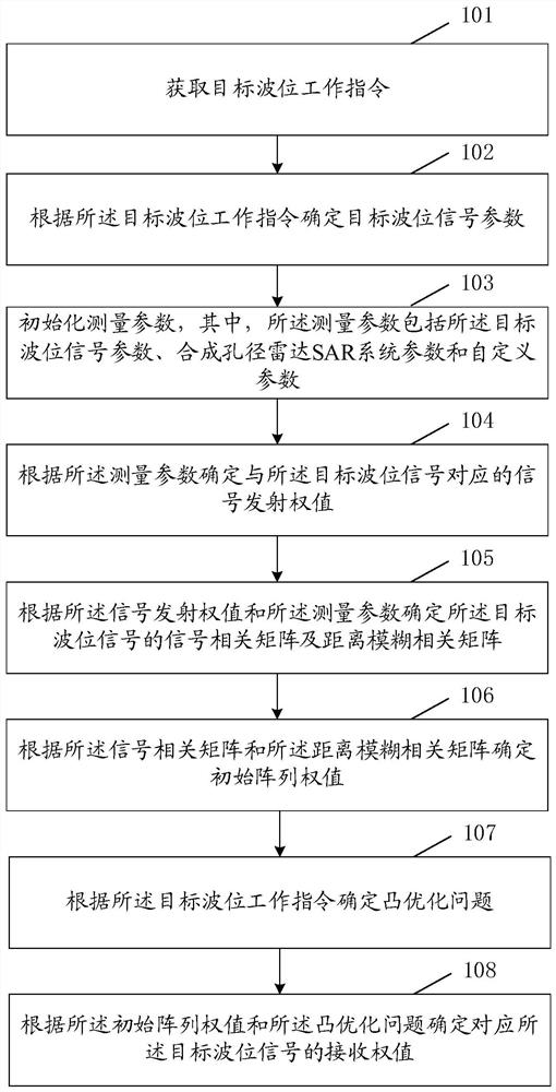
[0169] In this embodiment, the technical solution of the present application is further described and illustrated through specific suppression effects.

[0170] In this embodiment, the number of elements in the elevation direction of the satellite antenna is set to 22, and it works in the L-band. The selected wave position PRF is 3366Hz, the antenna installation angle is 30.5°, the near-end and far-end viewing angles of the observation beam are 25.1° and 27.3° respectively, and the orbital height is 607km.

[0171] figure 2 The transmit antenna pattern is shown, with weights only appended to the phase that causes the beam to change direction.

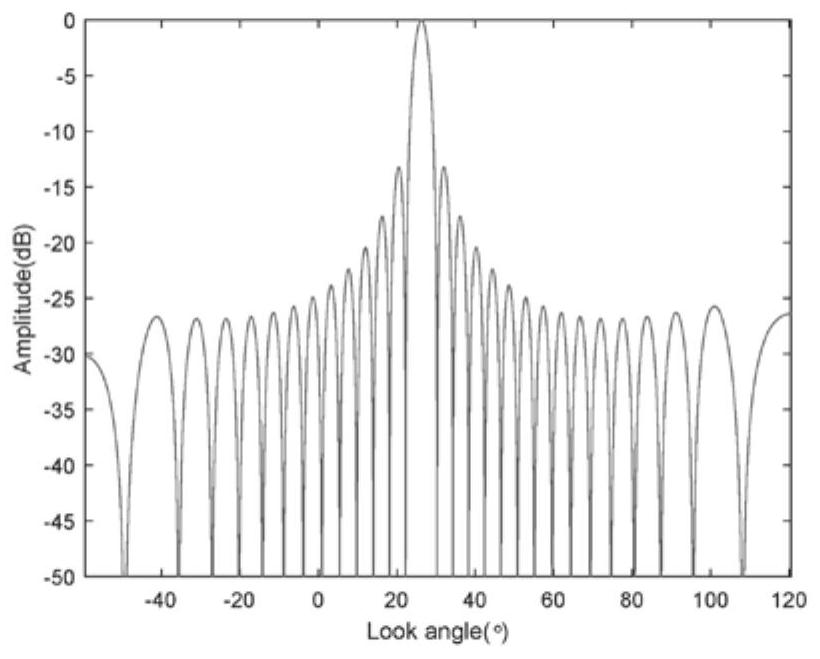
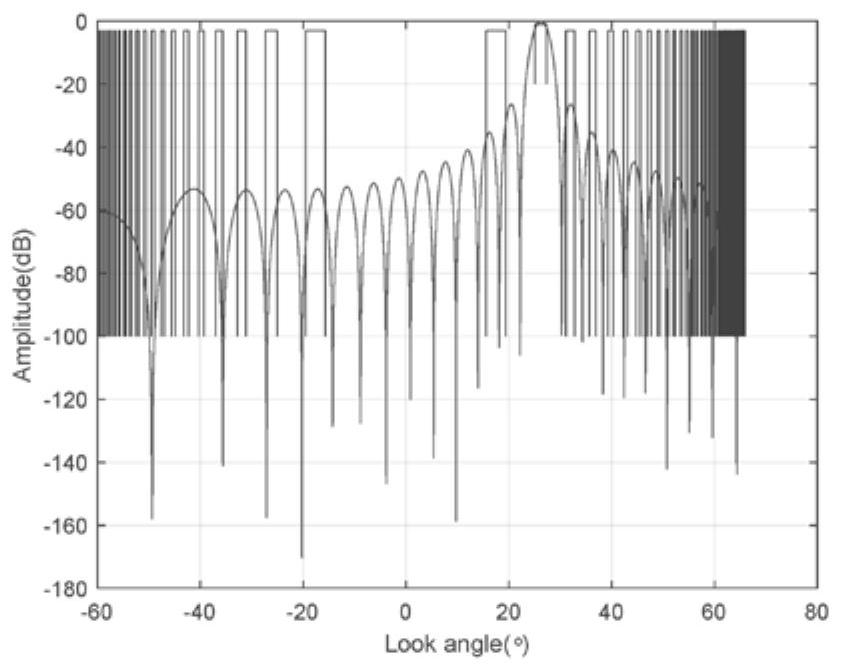
[0172] image 3 The two-way pattern of the antenna and the distribution of the distance ambiguity area are shown when the receiving pattern is the same as the transmitting pattern.

[0173] Figure 4 It shows the distance blur level at this time. The tolerable maximum value is generally -20dB, and the current distance blur level fa...

Embodiment 2

[0184] This embodiment further describes and illustrates the technical solution of the present application by emphasizing on suppressing the distance blur of a specific viewing angle. Also set the number of elements in the elevation direction of the satellite antenna to 22, and work in the L-band. The selected wave position PRF is 3366Hz, the antenna installation angle is 30.5°, the near-end and far-end viewing angles of the observation beam are 25.1° and 27.3° respectively, and the orbital height is 607km.

[0185] In the case that steps 101 to 104 are the same as in the first embodiment, according to step 104, the convex optimization problem is constructed as follows, setting p=1, μ 1 = 0.1, A 1 is the correlation matrix corresponding to the farthest viewing angle,

[0186] Figure 9 It shows the comparison between Example 2 and Example 1 to optimize the blur characteristics, and the blur at the far-end viewing angle is effectively suppressed, and the flexible control abi...


PUM


Abstract

The embodiment of the invention discloses a method for suppressing distance ambiguity based on antenna pattern synthesis. The method comprises the steps of obtaining a target wave position working instruction; determining a target wave position signal parameter according to the target wave position working instruction; initializing measurement parameters which comprise the target wave position signal parameter, an SAR system parameter and a user-defined parameter; determining a signal emission weight corresponding to the target wave position signal according to the measurement parameter; determining a signal correlation matrix and a range ambiguity correlation matrix of the target wave position signal according to the signal emission weight and the measurement parameters; determining an initial array weight according to the signal correlation matrix and the distance ambiguity correlation matrix; determining a convex optimization problem according to the target wave position working instruction; and determining a receiving weight corresponding to the target wave position signal according to the initial array weight and the convex optimization problem. The embodiment of the invention also discloses a device for suppressing distance ambiguity based on antenna pattern synthesis.

Description

technical field [0001] The present application relates to the technical field of synthetic aperture radar, in particular to a method and device for suppressing range ambiguity based on antenna pattern synthesis. Background technique [0002] Synthetic Aperture Radar (SAR) is an active microwave imaging device. Compared with optical radar, it has stronger penetration and can realize all-weather and all-weather earth observation. It has a wide range of applications in the field of remote sensing. SAR obtains high-resolution images by processing broadband pulse signals and azimuth Doppler signals. Due to the inevitable existence of side lobes in the antenna pitch pattern, echoes outside the surveying zone will also be received when receiving echoes, which will affect Ultimate image quality, this disturbance is known as distance blur. In order to improve the performance of SAR, range ambiguity must be suppressed. [0003] The range ambiguity suppression method based on antenna...

Claims


Application Information

Patent Timeline
IPC IPC(8): G01S13/90
Inventor 杨策欧乃铭刘大成王宇
Owner AEROSPACE INFORMATION RES INST CAS
Why Eureka
Try Eureka