
Temporal-mandibular joint CBCT image key point positioning method and device

A technology of temporomandibular joint and positioning method, applied in the field of medical image processing, can solve problems such as low efficiency and poor intelligence, and achieve the effects of alleviating low efficiency, improving positioning efficiency and high intelligence

Pending Publication Date: 2021-04-20
PEKING UNIV SCHOOL OF STOMATOLOGY
View PDF0 Cites 0 Cited by
  • Summary
  • Abstract
  • Description
  • Claims
  • Application Information

AI Technical Summary

Problems solved by technology

[0006] In view of this, the object of the present invention is to provide a method and device for locating key points of temporomandibular joint CBCT images, so as to alleviate the technical problems of low efficiency and poor intelligence in the existing methods of manually marking key point positions in CBCT images

Method used


Image

  • Temporal-mandibular joint CBCT image key point positioning method and device
  • Temporal-mandibular joint CBCT image key point positioning method and device
  • Temporal-mandibular joint CBCT image key point positioning method and device

Examples


Embodiment 1

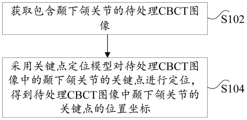
[0044] In order to facilitate the understanding of this embodiment, a method for locating key points of CBCT images of the temporomandibular joint disclosed in the embodiment of the present invention is first introduced in detail, see figure 1 A schematic flow chart of a method for locating key points of temporomandibular joint CBCT images is shown, which mainly includes the following steps:

[0045] Step S102, acquiring a CBCT image to be processed including the temporomandibular joint;

[0046] Step S104, using the key point positioning model to locate the key points of the temporomandibular joint in the CBCT image to be processed, and obtain the position coordinates of the key points of the temporomandibular joint in the CBCT image to be processed.

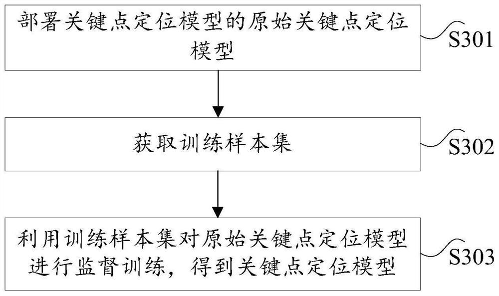
[0047] The aforementioned key point positioning model is obtained by training the original key point positioning model through training samples in advance.

[0048] The above-mentioned key points refer to positions with medica...

Embodiment 2

[0077] The embodiment of the present invention also provides a device for locating key points of CBCT images of temporomandibular joints. The method for locating the point, the device for locating the key point of the temporomandibular joint CBCT image provided by the embodiment of the present invention will be specifically introduced below.

[0078] Figure 8 It is a schematic diagram of a positioning device for a key point of a temporomandibular joint CBCT image according to an embodiment of the present invention, such as Figure 8 As shown, the positioning device of the key point of the temporomandibular joint CBCT image mainly includes: an acquisition unit 10 and a positioning unit 20, wherein:

[0079] An acquisition unit, configured to acquire a CBCT image to be processed including the temporomandibular joint;

[0080] The positioning unit is configured to use the key point positioning model to locate the key points of the temporomandibular joint in the CBCT image to b...


PUM


Abstract

The invention provides a temporal-mandibular joint CBCT image key point positioning method and device. The temporal-mandibular joint CBCT image key point positioning method comprises the steps of obtaining a to-be-processed CBCT image containing temporal-mandibular joints; and positioning key points of the temporal-mandibular joints in the to-be-processed CBCT image by adopting a key point positioning model to obtain the position coordinates of the key points of the temporal-mandibular joints in the to-be-processed CBCT image. According to the temporal-mandibular joint CBCT image key point positioning method, the key point positioning model is adopted to automatically position the temporal-mandibular joint key points in the to-be-processed CBCT image, so that the positioning efficiency of the temporal-mandibular joint key points in the to-be-processed CBCT image is improved, the intelligent degree is high, and the technical problems that an existing method for manually marking the key point positions in the CBCT image is low in efficiency and poor in intelligent degree are solved.

Description

technical field [0001] The invention relates to the technical field of medical image processing, in particular to a method and a device for locating key points of CBCT images of temporomandibular joints. Background technique [0002] The temporomandibular joint is the only left-right linkage joint in the whole body, and it is one of the most complex joints in the human body. It consists of the articular surface of the temporal bone, the condyle of the mandible, the articular disc between them, the joint capsule and the articular ligament around the joint. [0003] Temporomandibular joint disease refers to the general term for a group of diseases involving the temporomandibular joint and (or) masticatory muscle system, causing joint pain, snapping and limited mouth opening. In the clinical examination of temporomandibular joint disease, cone beam CT (Cone Beam CT, CBCT) has become the gold standard imaging method for bone changes. Quantitative analysis of bone structure usin...

Claims


Application Information

Patent Timeline
Patent Type & Authority Applications(China)
IPC IPC(8): G06T7/00G06T7/73G06N3/04G06N3/08
Inventor 李刚李居朋王颖慧马若晗
Owner PEKING UNIV SCHOOL OF STOMATOLOGY
Learn More