

An auxiliary guiding and positioning device for CT puncture
A technology for guiding positioning and positioning device, applied in the field of medical devices, can solve the problems of skewed puncture, inaccurate puncture, death, etc., and achieve the effect of avoiding deflection and error and having a wide range of applications
- Summary
- Abstract
- Description
- Claims
- Application Information
AI Technical Summary
Problems solved by technology
Method used
Image

Examples
Embodiment 1
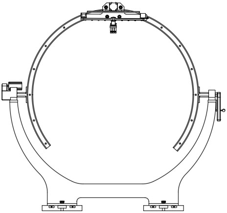
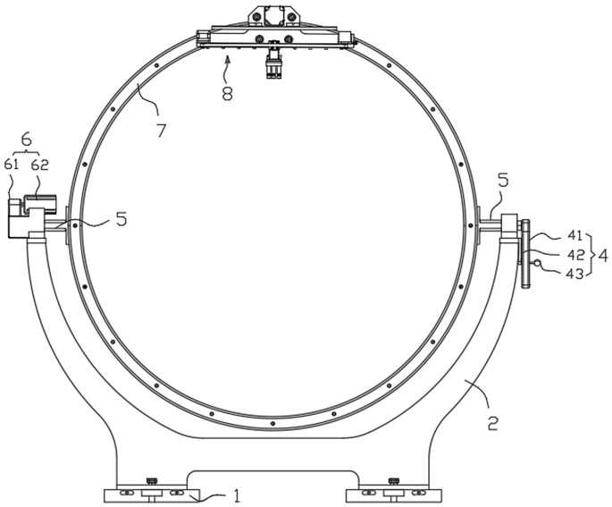
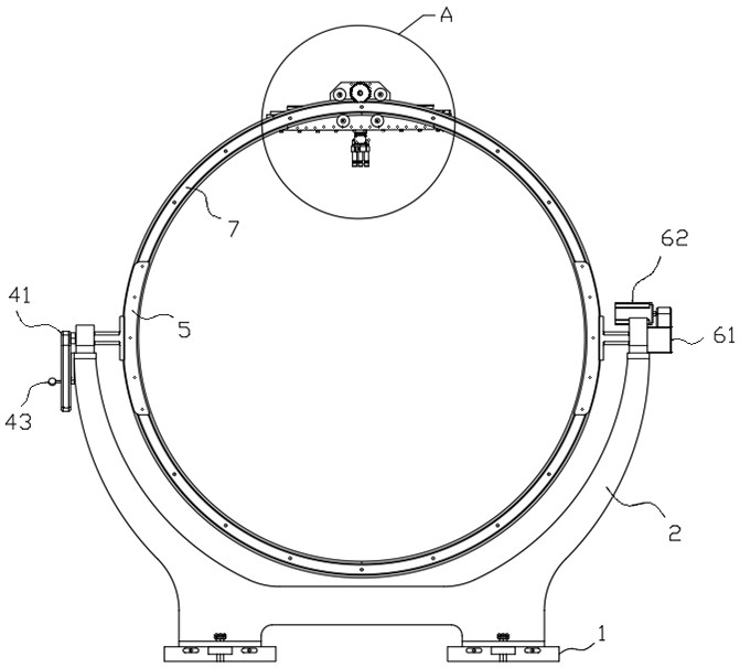
[0043] This embodiment aims to describe the process, principle and related structure of auxiliary guided puncture in combination with the existing CT machine. Specifically, this embodiment provides a positioning device for auxiliary guided puncture of CT, such as Figure 1-Figure 4 As shown, it is composed of a control mechanism and an actuator. The actuator includes a base 1, and a support frame 2 installed on the base 1 for supporting the positioning device. The support frame 2 has two rotatably connected with the positioning device. End, any end of the support frame 2 is provided with a locking mechanism 4 for limiting the deflection angle of the positioning device; A guide device 8 for indicating the space puncture angle is installed, and the guide device 8 includes a deflection drive mechanism sliding along the first guide rail 7, a first translation mechanism 87 and a second translation mechanism 88 installed vertically; On the second translation mechanism 88, a guide me...
Embodiment 2
[0055] As one of the refinement schemes of the present application, this embodiment is further refined on the basis of embodiment 1, such as Figure 4-Figure 6 As shown, the deflection drive mechanism includes a guide frame 82 as the installation and support body, the second servo motor 81 is detachably and fixedly installed on the guide frame 82, connected with the second servo motor 81 and positioned on the first guide rail 7 drives the driving wheel 83 connected to it, and a plurality of groups of stabilizing wheels 84 that are rotatably mounted on the guide frame 82 and located on the inner and outer sides of the first guide rail 7 respectively. When it is necessary to deflect in the radial plane, that is, in the plane of CT tomography, the second servo motor 81 drives the drive wheel 83 that is centrifugally and fixedly connected to it to rotate. Since the guide frame 82 is slidingly connected with the first guide rail 7, the Driven by the second servo motor 81, the entir...
Embodiment 3
[0057] This embodiment is an optimized structure proposed on the basis of Embodiment 2 for the situation where parallel puncture is required in the plane where the patient's scanning slice is located, specifically as Image 6 As shown, the first translation mechanism 87 includes a second guide rail 85 detachably and fixedly installed on the guide frame 82, a slide seat 872 that slides and is clamped on the second guide rail 85, and is respectively arranged on the The two ends of the second guide rail 85 are driven and connected to the third servo motor 86 and the follower 873 through a belt 871 ; the sliding seat 872 is detachably and fixedly connected to the belt 871 . When adjustment is required, the first translation mechanism 87 executes the parameters that need to be translated through the measurement of the CT machine, and translates the indication of the guide mechanism 89 from the ray pointing to the coaxial center of the CT machine and the auxiliary guiding and positio...
PUM
 Abstract
Description
Claims
Application Information