

Steel pipe tower rod hot zinc spraying system for electric power
A technology of hot-spraying zinc and steel pipes, applied in the direction of spraying devices, etc., can solve the problems of low spraying efficiency and labor-intensive hot-zinc spraying
- Summary
- Abstract
- Description
- Claims
- Application Information
AI Technical Summary
Problems solved by technology
Method used
Image

Examples
Embodiment 1
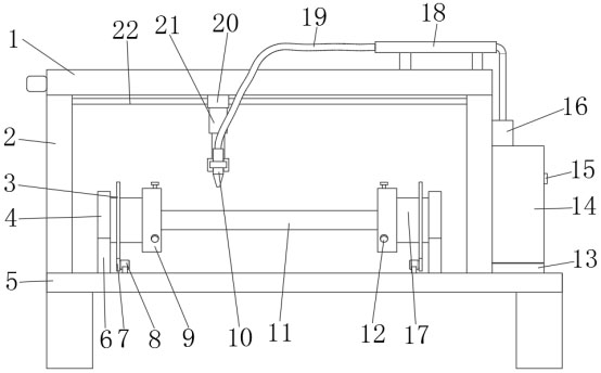
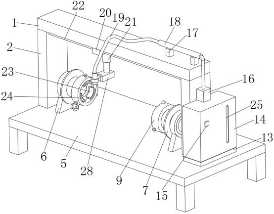
[0030] refer to Figure 1-6 , a steel pipe tower rod thermal spray zinc system for electric power, including a workbench 5, the top outer wall of the workbench 5 is fixed with two support columns 2 of the same size by screws, and the top of the support columns 2 is fixed with a top plate 1 by screws, The bottom outer wall of the top plate 1 has a rectangular groove, and the inner wall of the rectangular groove is slidingly connected with a T-shaped block 20, the left and right inner walls of the rectangular groove are connected with threaded rods through bearing rotation, and the right outer wall of the top plate 1 is fixed with a second screw. motor, and the output shaft of the second motor is connected with the threaded rod through a coupling, the T-shaped block 20 is connected with the threaded rod through threads, and the bottom outer wall of the T-shaped block 20 is fixed with an electric telescopic rod 21 by screws, and the electric telescopic The bottom outer wall of th...
Embodiment 2
[0040] refer to Figure 6 , a steel pipe tower rod thermal spray zinc system for electric power, including a workbench 5, the top outer wall of the workbench 5 is fixed with two support columns 2 of the same size by screws, and the top of the support columns 2 is fixed with a top plate 1 by screws, The bottom outer wall of the top plate 1 has a rectangular groove, and the inner wall of the rectangular groove is slidingly connected with a T-shaped block 20, the left and right inner walls of the rectangular groove are connected with threaded rods through bearing rotation, and the right outer wall of the top plate 1 is fixed with a second screw. motor, and the output shaft of the second motor is connected with the threaded rod through a coupling, the T-shaped block 20 is connected with the threaded rod through threads, and the bottom outer wall of the T-shaped block 20 is fixed with an electric telescopic rod 21 by screws, and the electric telescopic The bottom outer wall of the ...
PUM
 Abstract
Description
Claims
Application Information