
Rolling mill feeding device

A technology of feeding device and rolling mill, applied in the direction of guiding/positioning/aligning device, metal rolling, metal rolling, etc., can solve the problems of shaking state, unfavorable protection of worker safety, etc.

Active Publication Date: 2021-04-23
ZHEJIANG CHUANBOZHE METAL DECOUATION MATERIAL CO LTD
View PDF6 Cites 0 Cited by
  • Summary
  • Abstract
  • Description
  • Claims
  • Application Information

AI Technical Summary

Problems solved by technology

The above-mentioned patents have the following disadvantages: the plate entering the rolling mill is in a different stage of stress from the subsequent plate not entering the mill, so there is no limit device outside the rolling mill, and the plate is easily in a shaking state, which is not conducive to subsequent feeding and protection of worker safety

Method used


Image

  • Rolling mill feeding device
  • Rolling mill feeding device
  • Rolling mill feeding device

Examples


Embodiment Construction

[0030] The technical solution of this patent will be further described in detail below in conjunction with specific embodiments.

[0031] Embodiments of the present patent are described in detail below, examples of which are shown in the drawings, wherein the same or similar reference numerals designate the same or similar elements or elements having the same or similar functions throughout. The embodiments described below by referring to the figures are exemplary and are only used for explaining the patent, and should not be construed as limiting the patent.

[0032] In the description of this patent, it is to be understood that the terms "center", "upper", "lower", "front", "rear", "left", "right", "vertical", "horizontal", The orientation or positional relationship indicated by "top", "bottom", "inner", "outer", etc. is based on the orientation or positional relationship shown in the drawings, and is only for the convenience of describing this patent and simplifying the des...


PUM


Abstract

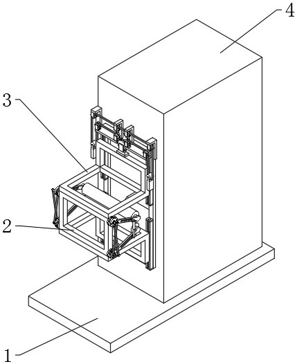
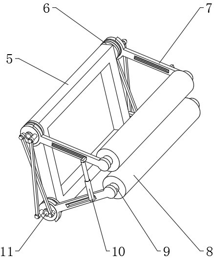
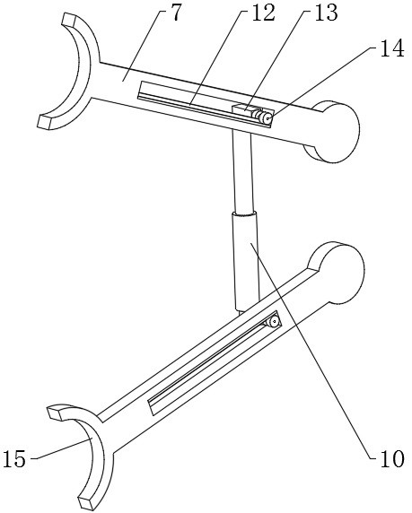
The invention discloses a rolling mill feeding device, relates to the field of rolling mill production, and aims to solve the problem that an existing device cannot clamp a plate in place after the plate enters a rolling mill. The rolling mill feeding device specifically comprises a bottom plate, a rolling mill body is fixedly connected to the outer wall of the top of the bottom plate, a levelling assembly is fixedly connected to the outer wall of one side of the inlet end of the rolling mill body, a clamping assembly is fixedly connected to the inner wall of the leveling assembly, and the clamping assembly comprises a transverse frame and four trunnions. The clamping assembly is arranged, a plate penetrates through the clamping assembly, the front end of the plate ejects a roller open, the roller moves, a fixed shaft drives an arm frame to rotate around a rotating plate, the rotating plate rotates, a first protruding column and a second protruding column drive the other rotating plate to rotate, and in other words, when the plate is pushed out forwards, the plate is assembled in a crossed mode through the connecting rods; and the two rotating plates on one side of the transverse frame can be driven to rotate at the same time, so that the swing synchronism of the arm frame is guaranteed, and meanwhile, plates can be clamped.

Description

technical field [0001] The invention relates to the field of rolling mill production, in particular to a rolling mill feeding device. Background technique [0002] In rolling mill production, feeding problems are faced with the dilemma of centering and protection. After the plate enters the rolling mill, due to the straightening work, the subsequent plate is prone to shaking and instant prying. It is necessary to add auxiliary devices to solve the above problems. [0003] After searching, the Chinese patent application number is 202010038942.4, which discloses a circumferential feeding device that can realize the continuous operation of the cross wedge rolling mill, including a feeding unit, a material receiving unit, and an arc-shaped slideway; the cross wedge rolling mill includes an upper roll And the lower roll, the upper roll includes a rolling section and a material receiving section, the outer periphery of the rolling section is an upper mold, and the material receivi...

Claims


Application Information

Patent Timeline
Patent Type & Authority Applications(China)
IPC IPC(8): B21B39/02B21B39/16B21B39/34
CPCB21B39/02B21B39/16B21B39/34
Inventor 田超叶寿喜许路坤谢舍东童秋明石付宗金伟建舒智广李祥张杰新陶宇俊
Owner ZHEJIANG CHUANBOZHE METAL DECOUATION MATERIAL CO LTD
Learn More