Glass rod polishing device

A technology of polishing device and glass rod, which is applied in the direction of surface polishing machine tools, grinding/polishing equipment, metal processing equipment, etc., which can solve the problems of reduced cleanliness of the environment around the surface of machine tools, reduced polishing effect, frequent cleaning by operators, etc. , to achieve the effect of reducing the amount of cleaning, beautiful appearance and smooth liquid circulation

Inactive Publication Date: 2021-04-23
浙江靖和光电科技股份有限公司
View PDF0 Cites 2 Cited by
  • Summary
  • Abstract
  • Description
  • Claims
  • Application Information

AI Technical Summary

Problems solved by technology

Due to the large oil basin, after the polishing liquid flows through the oil basin, the flow rate decreases and precipitation occurs. A large amount of cerium oxide is deposited in the oil basin, and the cerium oxide entering the circulation device is gradually reduced. Not only the polishing effect will be compromised, but also a large amount of expensive cerium oxide will be caused. Loss, increase polishing cost
Moreover, due to the lack of a polishing liquid collection device, a small amount of polishing liquid is thrown out with the rotating glass rod, which reduces the cleanliness of the surface of the machine tool and the surrounding environment, and the operator needs to clean it frequently

Method used


Image

  • Glass rod polishing device
  • Glass rod polishing device
  • Glass rod polishing device

Examples


Embodiment Construction

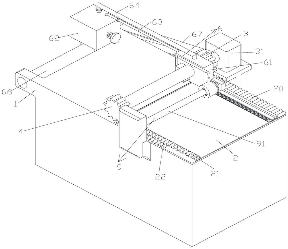
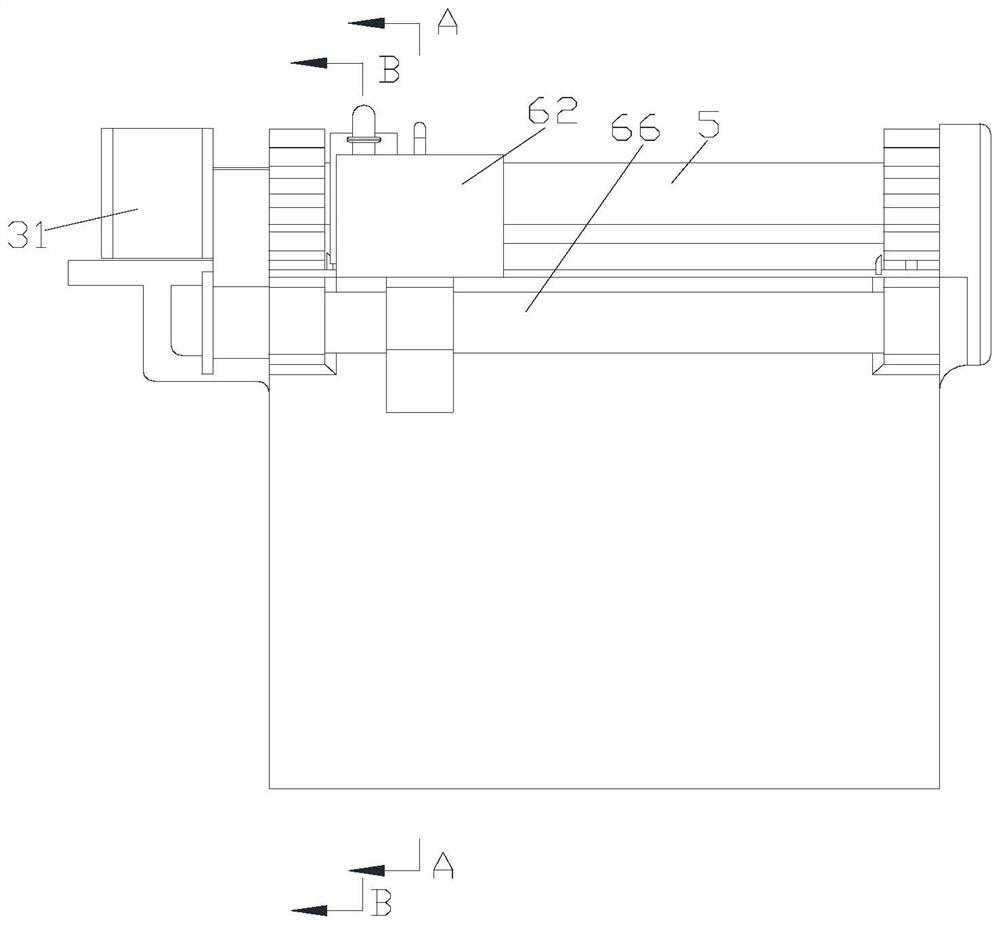
[0035] Such as Figure 1-14 As shown, a glass rod polishing device includes a base 1, a moving plate 2, a first large gear 3, a second large gear 4, a glass rod 5, and a first rotating shaft 30; the moving plate 2 is located on the base 1 and can move left and right along the lateral direction of the base 1; the first large gear 3 is arranged behind the central axis of the base 1, and the second large gear 4 is arranged in front of the central axis of the base 1; The glass rod 5 is arranged between the first large gear 3 and the second large gear 4, and the connection mode between the glass rod 5 and the first large gear 3 and the second large gear 4 is the prior art, and will not be repeated here; The first rotating shaft 30 is fixedly connected to the first large gear 3; the base 1 is provided with a motor 31 for the rotation of the first rotating shaft 30; the motor 31 is a prior art, and will not be repeated here.

[0036] The glass rod 5 is covered with a polishing devic...


PUM


Abstract

The invention discloses a glass rod polishing device which comprises a base, a moving plate capable of moving left and right along the base, a first bull gear, a second bull gear, a glass rod and a first rotating shaft, wherein the first bull gear and the second bull gear are arranged on the base; the glass rod is arranged in the first bull gear and the second bull gear in a penetrating mode; the first rotating shaft is arranged on the first bull gear; the glass rod is sleeved with a polishing device; and the polishing device comprises a polishing pressing head, a collecting box arranged outside the polishing pressing head in a sleeving mode, and a discharging box arranged on one side of the collecting box. According to the glass rod polishing device provided by the invention, the discharging box also synchronously moves in the same direction along with the polishing pressing head, so that a first pipeline and a second pipeline do not need to be arranged too long, the cost investment is reduced, liquid in the pipelines circulates more smoothly, and the appearance is more attractive; due to the effect of a first one-way valve, the flow direction of the liquid in the first pipeline and the second pipeline is more stable; and the first pipeline can also extract and recover the liquid collected in the collecting box into the discharging box, so that the waste of resources is reduced, and the recycling rate is increased.

Description

technical field [0001] The invention belongs to the technical field of glass rods, in particular to a glass rod polishing device. Background technique [0002] In the micro-channel plate manufacturing process, before the glass tube rod assembly is drawn into fiber filaments, the surface of the rounded glass rod needs to be polished by a polishing machine. Existing polishing machines generally grind the surface back and forth with wool felt to realize polishing by rotating the glass rod. During the polishing process, the wool felt needs to be infiltrated with a polishing solution containing cerium oxide to enhance the polishing effect. The polishing solution containing cerium oxide is continuously input into the wool felt by the circulation device through the pipe, then flows out from the pressure head and drops into the oil basin of the machine tool, and finally enters the polishing solution circulation device to complete the circulation process. Due to the large oil basin...

Claims


Application Information

Patent Timeline
Patent Type & Authority Applications(China)
IPC IPC(8): B24B29/08B24B57/02B24B57/00
Inventor 张厦础
Owner 浙江靖和光电科技股份有限公司
Why Eureka
Try Eureka