Manipulator locating, guiding and calibrating method based on machine vision cooperation

A technology of machine vision and calibration method, applied in manipulators, program-controlled manipulators, manufacturing tools, etc., can solve the problems of complex calibration process, high precision requirements of calibration blocks, and difficult to complete calibration, etc., and achieve the effect of simple calibration process

Pending Publication Date: 2021-04-23
ANHUI JEE AUTOMATION EQUIP CO LTD
View PDF10 Cites 7 Cited by
  • Summary
  • Abstract
  • Description
  • Claims
  • Application Information

AI Technical Summary

Problems solved by technology

[0004] In the prior art, the calibration process is complicated, and the accuracy of the calibration block is high.

Method used


Image

  • Manipulator locating, guiding and calibrating method based on machine vision cooperation
  • Manipulator locating, guiding and calibrating method based on machine vision cooperation
  • Manipulator locating, guiding and calibrating method based on machine vision cooperation

Examples


Embodiment Construction

[0020]The present invention will be described in detail below with reference to the drawings.

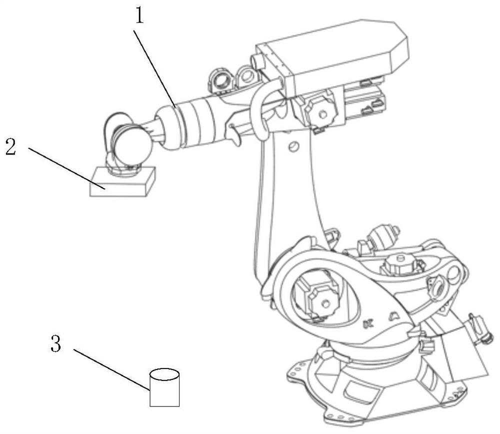
[0021]The present invention relates to a visual system positioning guidance calibration method, and the visual system used includes a controller, a camera with a lens, and a light source.

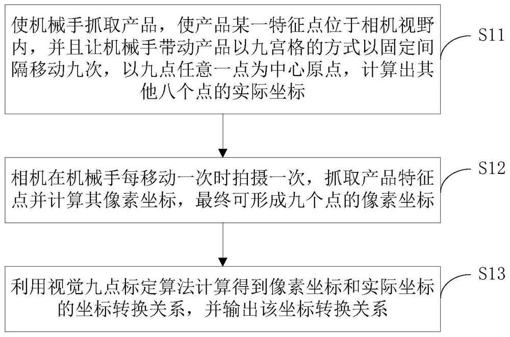
[0022]Combined referencefigure 1 The calibration method of the present invention based on the machine-based visual mating robot is included in the following steps:

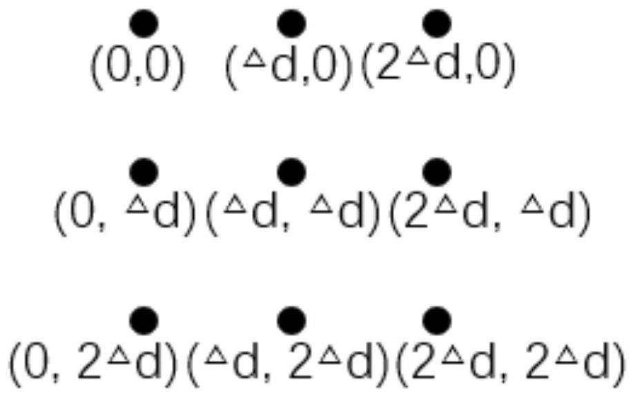
[0023]S11, using a robot to grab the product, enabling a characteristic point in the camera in the camera, and allows the robot to move the product in a nine-rich manner, the moving distance is △ D, at nine o'clock as the center origin, calculate other The actual coordinates of eight points;

[0024]S12, the camera captures the characteristics of the characteristics and calculates the pixel coordinates of the product when the robot is moved once, grab the product feature point and calculate its pixel coordinates.

[0025]S13, using the visual nine-point ...


PUM


Abstract

The invention discloses a manipulator locating and guiding method and a calibration method based on machine vision cooperation. The calibration method comprises the steps of grabbing a product through a manipulator, so that a certain feature point of the product is located in the visual field of a camera, the product is driven by the manipulator to move for nine times in a nine-square mode, and the moving distance is delta d; taking any one of nine points as a central origin, and calculating actual coordinates of the other eight points; shooting once with a camera when the manipulator is moved once, capturing feature points of the product, calculating the pixel coordinates of the feature points, and finally forming the pixel coordinates of the nine points; and calculating a coordinate conversion relationship between pixel coordinates and actual coordinates by using a visual nine-point calibration algorithm. The calibration method is simple in calibration process, calibration blocks are not needed, and calibration is carried out only through the corresponding relation between image points. According to the guiding method, the offset of a locating point can be calculated according to the rotating center point calculated in a virtual coordinate system, and therefore the manipulator can be guided to adjust the grabbing position of the product.

Description

Technical field[0001]The present invention relates to a method of positioning guidance and calibration method based on machine visual mating robot.Background technique[0002]With the development of technology, market users have become higher and high, and the traditional positioning method can no longer meet the needs of users, and therefore, the machine visual positioning technology is successively obtained.[0003]The relationship between the unified visual coordinate system and the robot coordinate system is often referred to as calibration. The calibration method of the conventional camera is to utilize the structural information of the scene, which is usually a structure, a calibration block having a high machining accuracy as a directional reference, a corresponding relationship between the spatial point and the camera point, and then passes Optimization algorithm extraction parameters.[0004]In the prior art, the calibration process is complex, and the accuracy requirements of th...

Claims


Application Information

Patent Timeline
IPC IPC(8): B25J9/18B25J13/08
CPCB25J9/1605B25J9/1692B25J9/1697B25J13/088
Inventor 刘蕾汪波周闯任永强王光磊屠庆松
Owner ANHUI JEE AUTOMATION EQUIP CO LTD
Why Eureka
Try Eureka