Pump head of diaphragm booster pump, diaphragm booster pump and water treatment device

A diaphragm pressurization and pump head technology, which is applied to parts of pumping devices for elastic fluids, pumps with flexible working elements, pumps, etc., can solve the problems of small flow, large vibration and noise, etc., to improve flow, Reduce vibration and noise, reduce vibration effect

Inactive Publication Date: 2021-04-23
SHENZHEN ANGEL DRINKING WATER IND GRP
View PDF2 Cites 3 Cited by
  • Summary
  • Abstract
  • Description
  • Claims
  • Application Information

AI Technical Summary

Problems solved by technology

[0010] In order to overcome the technical problems existing in the prior art, this application provides a pump head of a diaphragm booster pump, a

Method used


Image

  • Pump head of diaphragm booster pump, diaphragm booster pump and water treatment device
  • Pump head of diaphragm booster pump, diaphragm booster pump and water treatment device
  • Pump head of diaphragm booster pump, diaphragm booster pump and water treatment device

Examples


Embodiment Construction

[0059] The technical solutions of the present application are clearly and completely described below in conjunction with the accompanying drawings in the embodiments of the present application. Apparently, the described embodiments are part of the embodiments of the present application, not all of them. Based on the embodiments in this application, all other embodiments obtained by those skilled in the art without making creative efforts belong to the scope of protection of this application.

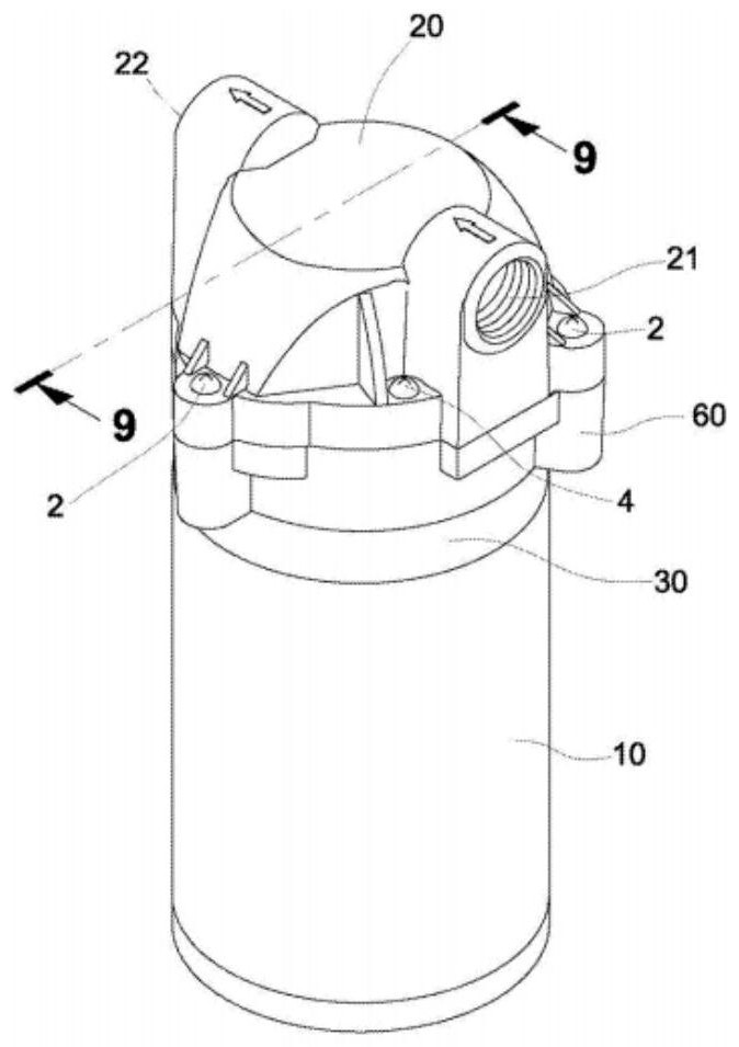
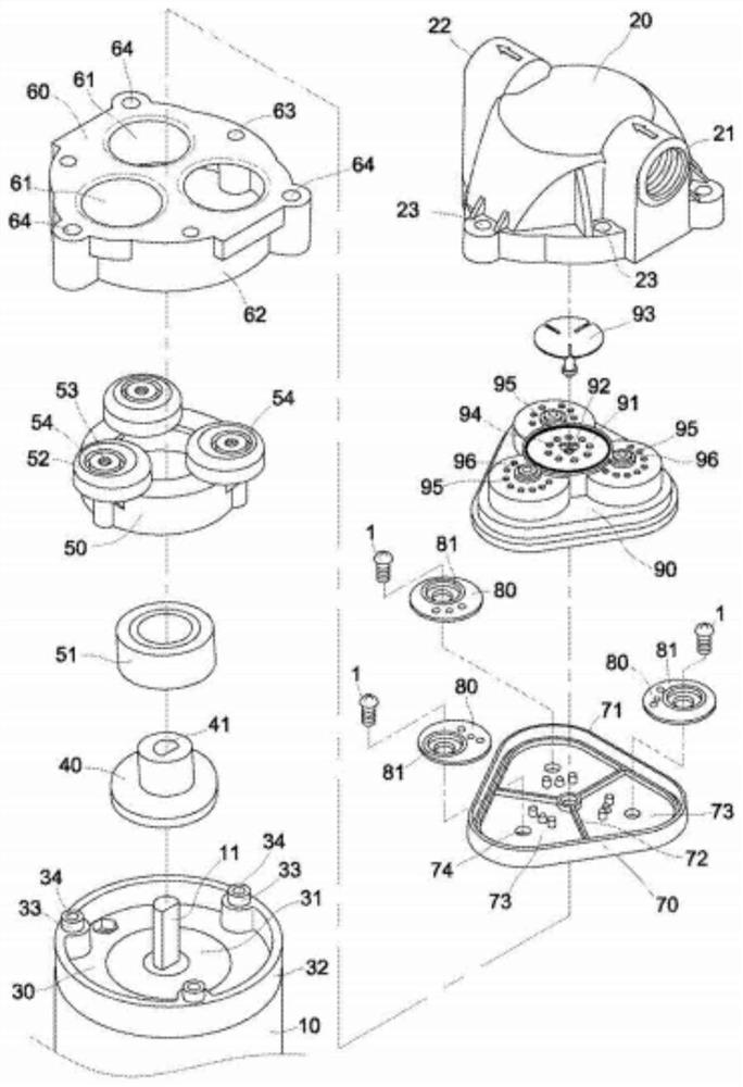
[0060] like image 3 and Figure 4 As shown, the present embodiment provides a pump head of a diaphragm booster pump, and the pump head includes: a piston chamber 6, a diaphragm 3, a first eccentric wheel 8 and a second eccentric wheel 11, a first balance wheel 9, a second eccentric wheel Two balance wheel 10, motor shaft 14.

[0061] Wherein the eccentric assembly includes the motor shaft 14 , the first eccentric wheel 8 and the second eccentric wheel 11 .

[0062] The balance wheel ...


PUM


Abstract

The invention relates to a pump head of a diaphragm booster pump, the diaphragm booster pump and a water treatment device. The pump head comprises a piston chamber, wherein a pressurizing cavity is formed in the inner wall of the piston chamber; a diaphragm piece, sealed to form the pressurizing cavity, wherein the pressurizing cavity is expanded or compressed in the radial direction; eccentric wheels, including the first eccentric wheel and the second eccentric wheel, wherein the eccentricity of the first eccentric wheel is opposite to the eccentricity of the second eccentric wheel, and a first balance wheel and a second balance wheel which correspond to the first eccentric wheel and the second eccentric wheel respectively move in opposite directions. By the radial movements of the diaphragm piece, the pressurizing cavity is expanded or compressed, the flow of the diaphragm booster pump is increased, and vibration and noise generated when the diaphragm booster pump works are reduced.

Description

technical field [0001] The present application relates to the technical field of water treatment, in particular to a pump head of a diaphragm booster pump, a diaphragm booster pump, and a water treatment device. Background technique [0002] At present, the commonly used diaphragm booster pumps cause volume changes through the periodic movement of the diaphragm, which drives the rubber valve to periodically close and open the water inlet and outlet on the valve seat to achieve supercharging. [0003] The motor of the diaphragm booster pump drives the eccentric wheel to rotate, and the balance wheel cannot rotate because it is restricted, so the three balance wheels can only produce axial reciprocating motions in sequence, and the deformation area of ​​the diaphragm will be synchronized by the axial reciprocating motion of the balance wheel The axial expansion or compression movement of the diaphragm, when the diaphragm piston action area moves to the expansion direction, the...

Claims


Application Information

Patent Timeline
IPC IPC(8): F04B43/04F04B53/00
CPCF04B43/04F04B43/0054F04B53/00F04B53/001F04B43/026F05B2210/11F04B9/045
Inventor 李国平王娟丘春辉
Owner SHENZHEN ANGEL DRINKING WATER IND GRP
Why Eureka
Try Eureka