Return air heat recovery and dust online cleaning evaporator module and heat pump drying device

An evaporator module and heat recovery technology, applied in the direction of cleaning heat transfer devices, evaporator/condenser, drying, etc., can solve the problems of huge initial investment, increased energy consumption of dust removal devices, etc., to overcome pollution and reduce heating power Large, high energy efficiency ratio effect

Pending Publication Date: 2021-04-23
广州万二二麦工程技术有限公司
View PDF0 Cites 6 Cited by
  • Summary
  • Abstract
  • Description
  • Claims
  • Application Information

AI Technical Summary

Problems solved by technology

However, these dedusting devices not only have a huge initial investment, which is as large as a heat pump unit, but also must use a high-power centrifugal fan during operation due to the increase in airflow resistance, resulting in a significant increase in energy consumption of the dedusting device, and the energy consumption of the dedusting device. heat pump unit

Method used


Image

  • Return air heat recovery and dust online cleaning evaporator module and heat pump drying device
  • Return air heat recovery and dust online cleaning evaporator module and heat pump drying device
  • Return air heat recovery and dust online cleaning evaporator module and heat pump drying device

Examples


Embodiment 1

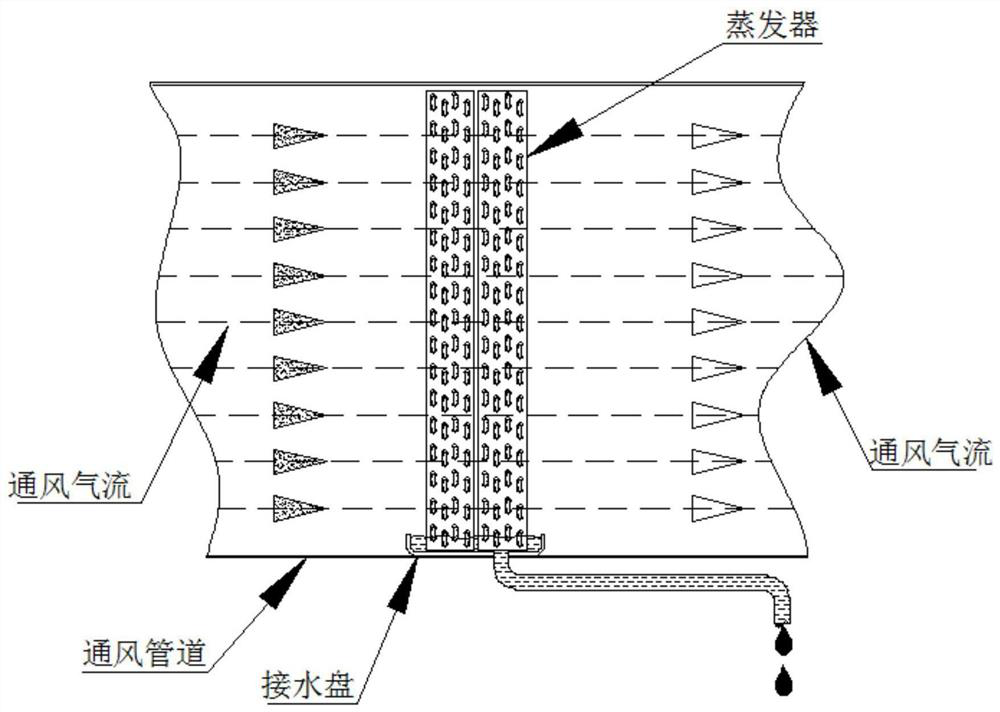
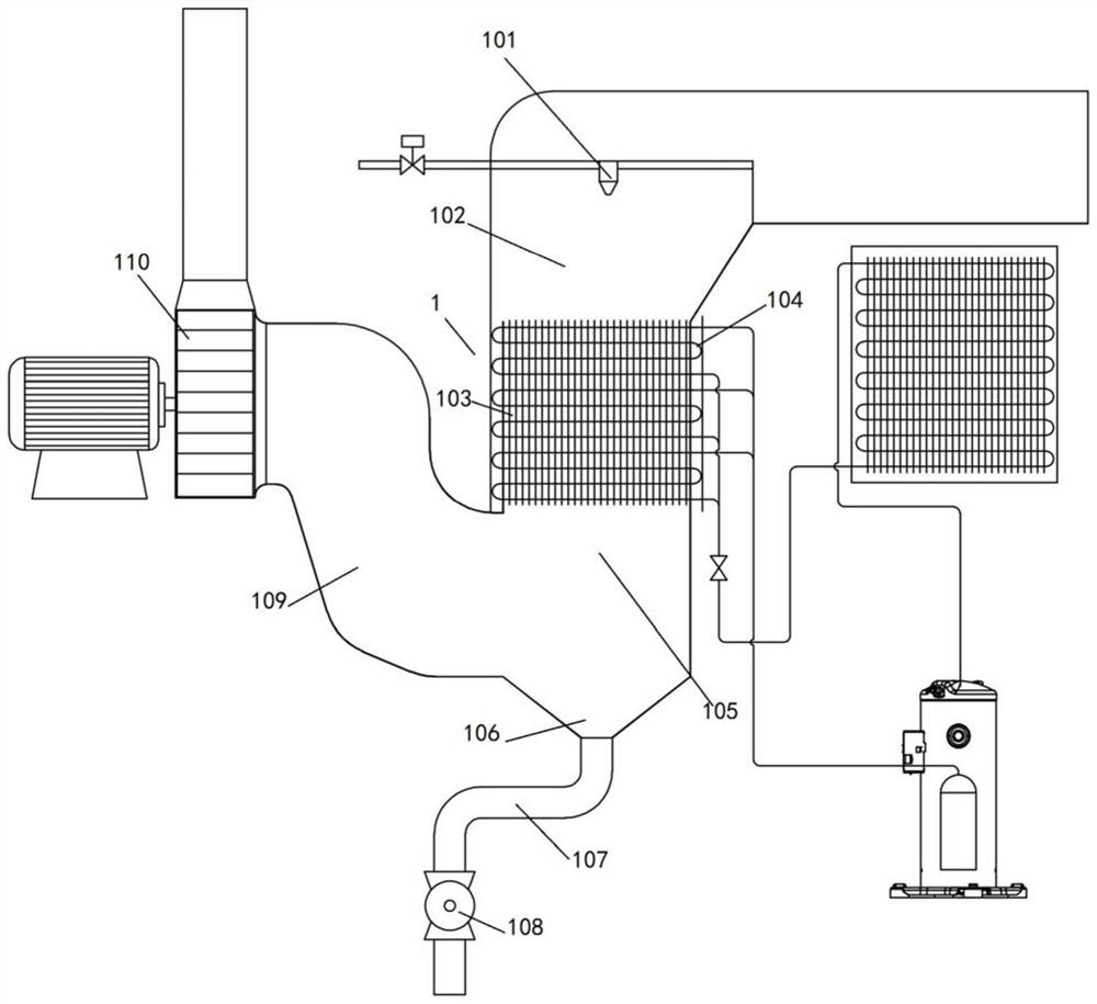
[0049] Please refer to Figure 3 to Figure 5 , an evaporator module 1 for return air heat recovery and online dust cleaning, the air duct of the evaporator module 1 is changed from the traditional horizontal setting to the vertical setting, and the water connection of the jacking evaporator in the traditional evaporator module is cancelled. The tray, that is, the bottom of the evaporator module 1 is a non-contact water receiving tray with a downward open air path structure, so that the warm and humid return air from the drying device can flow through the evaporator smoothly from top to bottom. Specifically, the evaporator module 1 includes at least one evaporator 104, the air duct of the evaporator module 1 is a vertical air duct, and the warm and humid return air from the drying device passes through the vertical air duct from above to Flow down through the evaporator 104; the vertical air channel includes a water mist mixing section 102, an endothermic adsorption section 103...

Embodiment 2

[0068] This embodiment is further improved on the basis of Embodiment 1.

[0069] In this embodiment, the lower end of the sewage tank 106 communicates with the sewage pool through a sewage pipe. During operation, since the return air in the air-pollution separation section 105 is drawn out by the centrifugal fan 110, the air-pollution separation section 105 generates negative pressure, which is not conducive to discharging the mud into the sewage tank. Therefore, need to do further improvement to blowdown pipe.

[0070] As an example, please refer to Figure 3 to Figure 5 , the outlet of the sewage discharge pipe 107 is vertically downward, and the sewage discharge pipe 107 is provided with valves, such as electric valves, ball valves 108 and the like.

[0071] As another example, please refer to Figure 6 , the sewage discharge pipe 107' is a U-shaped pipe. The sewage discharge outlet of this U-shaped pipe is different from the above-mentioned embodiment. Its sewage disch...

Embodiment 3

[0073] This embodiment provides a heat pump drying device, including a heat pump unit, and the heat pump unit includes the return air heat recovery and dust online cleaning evaporator module 1 described in any of the above embodiments. In this embodiment, there is no specific limitation on which field the heat pump drying device is applied to.


PUM


Abstract

The invention relates to a return air heat recovery and dust online cleaning evaporator module and a heat pump drying device. The evaporator module comprises at least one evaporator. An air duct of the evaporator module is a vertical air duct; the bottom of the evaporator is of a downward open type air path structure of a non-contact type water pan; and warm and wet return air from a drying device flows through the evaporator from top to bottom through the vertical air duct. The gravity separation effect and the return air entrainment effect are fully utilized, so that the stripping and falling effects of mud attached to evaporator fins for heat recovery are improved, the water mist particle downward flushing speed and the capacity of flushing the mud attached to the evaporator fins during spray cleaning are improved, and the air-sewage separation effect below the evaporator is improved.

Description

technical field [0001] The invention relates to the technical field of grain drying, in particular to an evaporator module for return air heat recovery and online dust cleaning and a heat pump drying device. Background technique [0002] When drying devices such as grain dryers are in operation, dry hot air (for example, 70°C) is sent into the hot air channel of the drying section of the dryer, penetrates through the metal orifice plate into the grain layer in the lower grain trough, and diffuses in the gap between grain particles Movement, heating the grain grains, evaporating the moisture inside the grain grains, turning them into water vapor and mixing them into a warm and humid air flow, and then passing through the metal orifice plate opposite the lower grain trough to discharge into the exhaust channel, and converging into the high enthalpy warm and humid air of the dryer Out of the wind, discharged to the environment. [0003] In grain mechanized drying devices such ...

Claims


Application Information

Patent Timeline
Patent Type & Authority Applications(China)
IPC IPC(8): F26B21/00F26B25/00F25B39/02F28G9/00
CPCY02P70/10
Inventor 薛世山周萍周孑民李成伟徐学冲马骥韦林林吴飞飞应小勇诸葛水明王恒胡用刘帅帅王庆伦
Owner 广州万二二麦工程技术有限公司
Why Eureka
Try Eureka