High-power high-voltage electric heater

A high-voltage, high-power technology, which is applied in the direction of ohmic resistance heating parts, heating element shape, ohmic resistance electrode, etc., can solve the problem of increased installation space requirements for electric heating elements, large power requirements for electric heaters, and electric heating. The problem of large heat loss of the device is solved, and the electrode connection structure is safe and reliable, the operation is convenient, and the actual pressure is reduced.

Active Publication Date: 2021-04-23
WUXI HENGYE ELECTRICAL HEATER EQUIP
View PDF1 Cites 0 Cited by
  • Summary
  • Abstract
  • Description
  • Claims
  • Application Information

AI Technical Summary

Problems solved by technology

The power requirement of the electric heater is large, and the installation space requirement of the internal electric heating element is correspondingly increased; under the dual working conditions of high working pressure and temperature, the strength requirement for the container of the electric heater is extremely high, which makes the existing technology The method of increasing the volume by increasing the diameter of the container often cannot meet the requirements of use, because under the requirement of strength, the increase of the diameter of the container will inevitably put forward higher requirements for the thickness of the container; on the other hand, the existing electric heater is usually cooled by water Due to the low boiling point of water, the temperature difference between it and the circulating medium is very large, resulting in large heat loss and large thermal stress of the electric heater, which seriously affects its long-term use.

Method used


Image

  • High-power high-voltage electric heater
  • High-power high-voltage electric heater
  • High-power high-voltage electric heater

Examples


Embodiment Construction

[0032] The specific implementation manner of the present invention will be described below in conjunction with the accompanying drawings.

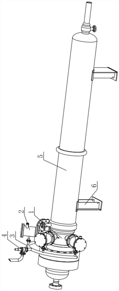
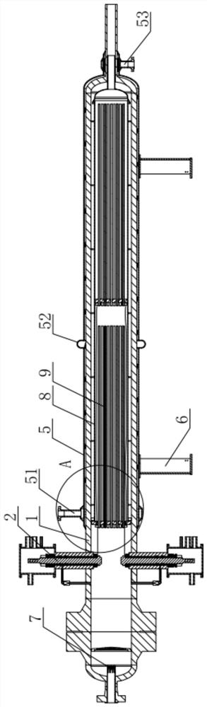
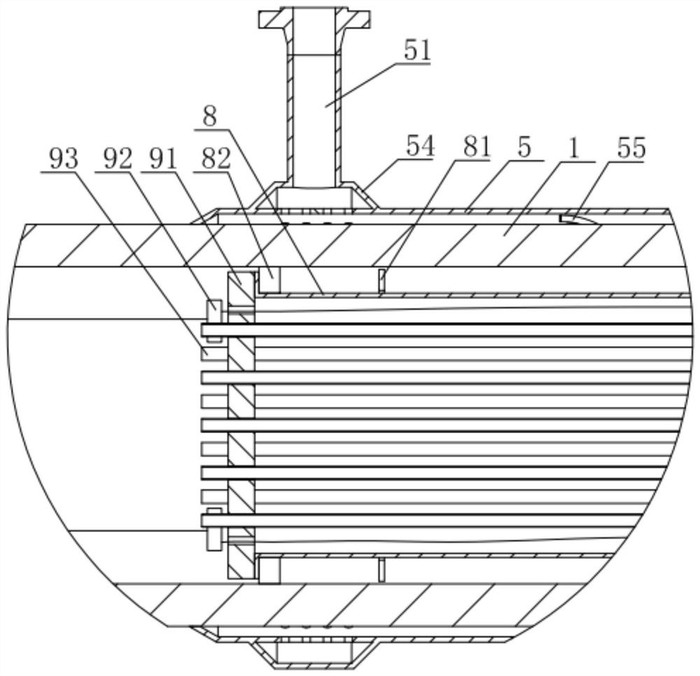
[0033] Such as figure 1 with figure 2 As shown, the high-power high-voltage electric heater of this embodiment includes a casing 1 that runs through the front and back, and the outer wall of the casing 1 is fitted with a casing 5 at intervals to form a closed space, and the two ends of the casing 5 are respectively provided with oil inlets 53 And the oil outlet 51; the inside of the shell 1 is sleeved with a pipe body 8 along the length direction, and multiple sets of heating components 9 are installed in the pipe body 8 at intervals along the length direction; the wall of the shell 1 located in front of the shell 5 A plurality of electrode assemblies 2 of the same group of power supplies are installed at intervals along the circumferential direction, and multiple sets of heating assemblies 9 are electrically connected to the group of po...


PUM


Abstract

The invention relates to a high-power high-voltage electric heater. The electric heater comprises a shell which is through in the front-back direction, the outer wall face of the shell is sleeved with an outer shell at intervals to form a closed space, and an oil inlet and an oil outlet are formed in the two ends of the outer shell respectively; a pipe body is fixedly sleeved with the shell in the length direction, and multiple sets of heating assemblies are installed in the pipe body in the length direction at intervals; a plurality of electrode assemblies of the same group of power supplies are arranged on the wall surface of the shell in front of the shell at intervals along the circumferential direction; the plurality of groups of heating assemblies are electrically connected with the group of power supplies; and a rectification assembly is installed at an inlet in the shell. According to the electric heater, the multiple heating assemblies are arranged at intervals in the length direction, the power of the electric heater is effectively improved, and meanwhile the overall diameter size of the electric heater is greatly reduced; multiple groups of heating assemblies adopt the same group of power supply, and the leakage risk is effectively reduced by reducing the number of the electrode introducing devices; and an outer wall surface oil cooling mode is also adopted, so that the electric heater is small in overall heat loss, small in thermal stress and good in practicability.

Description

technical field [0001] The invention relates to the technical field of electric heaters, in particular to a high-power high-voltage electric heater. Background technique [0002] The electric heater is one of the important equipments for the performance testing of aviation aircraft and its components. According to the test requirements, it requires high working pressure and high heating power. The power requirement of the electric heater is large, and the installation space requirement of the internal electric heating element is correspondingly increased; under the dual working conditions of high working pressure and temperature, the strength requirement for the container of the electric heater is extremely high, which makes the existing technology The method of increasing the volume by increasing the diameter of the container often cannot meet the requirements of use, because under the requirement of strength, the increase of the diameter of the container will inevitably pu...

Claims


Application Information

Patent Timeline
Patent Type & Authority Applications(China)
IPC IPC(8): H05B3/02H05B3/03H05B3/40
CPCH05B3/02H05B3/03H05B3/40
Inventor 赵钧王春花赵成旺
Owner WUXI HENGYE ELECTRICAL HEATER EQUIP
Why Eureka
Try Eureka