Stringing device for food processing
A food processing and skewering technology, which is applied in the direction of processed meat, meat processing equipment, applications, etc., can solve the problems of poor working environment, low food surface temperature, unfavorable manual operation, etc., and achieve the effect of improving work efficiency and reducing labor force
- Summary
- Abstract
- Description
- Claims
- Application Information
AI Technical Summary
Problems solved by technology
Method used
Image
Examples
Embodiment 1
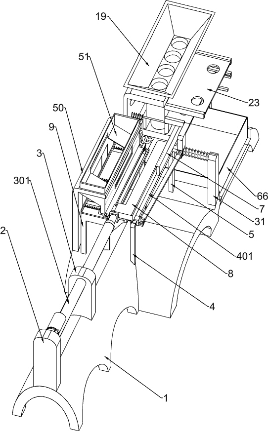
[0033] Such as figure 1 and figure 2 As shown, it includes a base 1, a first support plate 2, a second support plate 3, a pushing mechanism, a linkage mechanism, a feeding mechanism and a discharging mechanism. The first support plate 2 is fixedly installed on the left end of the base 1, and the second support plate The plate 3 is fixedly installed above the base 1, the second support plate 3 is on the right side of the first support plate 2, the pushing mechanism is installed on the base 1, the pushing mechanism is on the right side of the first support plate 2, and a part of the pushing mechanism is installed on the On the first support plate 2 and the second support plate 3, the linkage mechanism is installed on the pushing mechanism, one end of the pushing mechanism is connected with the blanking mechanism, and the discharging mechanism is installed on the pushing mechanism and the blanking mechanism.
[0034] The base 1 plays a fixed role for the whole device, and the f...
Embodiment 2
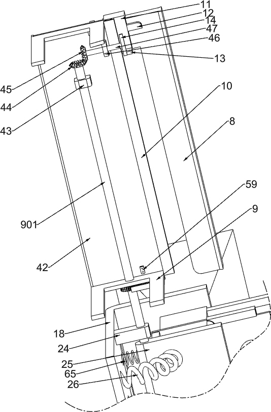
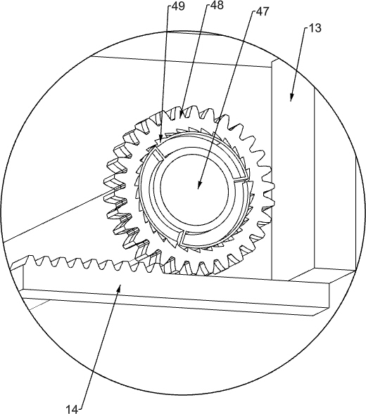
[0036] Such as figure 2 and image 3 As shown, the pushing mechanism includes an electric push rod 301, a first pillar 4, a first slide bar 401, a second pillar 5, a third pillar 6, a first slide plate 7, an L bar 8, a U-shaped frame 9, and a second slide plate 10. Top block 11, connecting block 12, first connecting plate 13, first rack 14, short plate 15, first sliding column 16, pressure plate 1601 and first spring 17, electric push rod 301 is fixedly installed on the first branch On the plate 2 and the second support plate 3, the first support 4 is fixedly installed on the base 1, the first support 4 is on the side of the second support plate 3, the second support 5 is fixedly installed on the base 1, and the second support 5 is on the On the right side of the first pillar 4, the third pillar 6 is installed on the right end of the base 1, and the first slide bar 401 is fixedly installed between the top end of the first pillar 4 and the top end of the third pillar 6, and t...
Embodiment 3
[0045] Such as Figure 9 and Figure 10 Shown, also include the second L frame 50, the second blanking box 51, the fixed plate 52, the fifth slide plate 53, the first extension spring 54, the big block 55, the fourth sliding column 5501, the sixth spring 5502, the small Block 5503, the second connecting rod 56, the fifth rack 57 and the third gear 58, the second L frame 50 is fixedly installed above the rear side of the base 1, the second L frame 50 is on the left side of the first L frame 18, the second The blanking box 51 is fixedly installed on the top of the second L frame 50, the fixed plate 52 is fixedly installed on the rear end of the rectangular plate 42, the fifth slide plate 53 is slidably installed on the upper side of the rectangular plate 42, and the three first extension springs 54 are fixedly installed on the upper side of the rectangular plate 42. Between the fifth slide plate 53 and the fixed plate 52, a large block 55 is fixedly installed on both sides of t...
PUM
 Abstract
Description
Claims
Application Information
 - R&D
- Intellectual Property
- Life Sciences
- Materials
- Tech Scout
- Unparalleled Data Quality
- Higher Quality Content
- 60% Fewer Hallucinations
Browse by: Latest US Patents, China's latest patents, Technical Efficacy Thesaurus, Application Domain, Technology Topic, Popular Technical Reports.
© 2025 PatSnap. All rights reserved.Legal|Privacy policy|Modern Slavery Act Transparency Statement|Sitemap|About US| Contact US: help@patsnap.com


