
Post-processing equipment for infant wet tissue production
A processing equipment, infant technology, applied in textile processing machine accessories, textiles and papermaking, extrusion liquid/gas/steam removal other than rollers, etc., can solve problems such as uneven and insufficient spraying, and improve products High quality, simple structure, and the effect of improving the efficiency of static electricity removal
- Summary
- Abstract
- Description
- Claims
- Application Information
AI Technical Summary
Problems solved by technology
Method used
Image

Examples
Embodiment 1
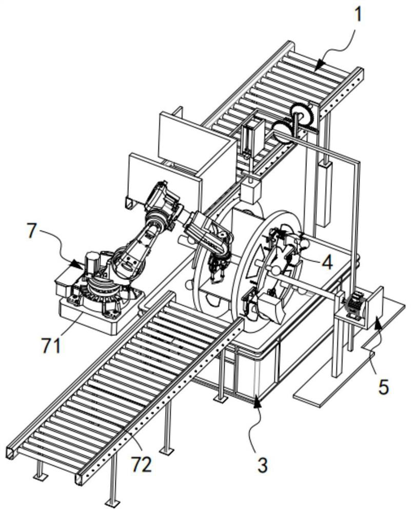
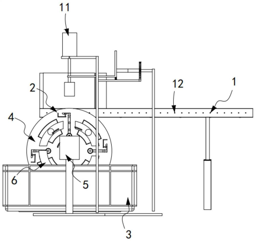
[0063] like figure 1 and figure 2 As shown, a polyester staple fiber post-processing device includes an input device 1, an electrostatic treatment device 2 arranged at the output end of the input device 1, and an electrostatic liquid storage box 3 arranged below the electrostatic treatment device 2;
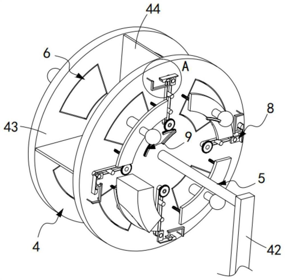
[0064] The electrostatic treatment device 2 includes a station switching mechanism 4, a driving mechanism 5 for driving the station switching mechanism 4 to rotate in a circle, a draining mechanism 6 for draining the destaticized fiber cluster 10, and a For the output mechanism that will complete the output work of the fiber group after the static electricity removal, the station switching mechanism 4 is sequentially provided with a material receiving station 201, a pretreatment and breaking up station 202, a static electricity removal station 203 and a draining station along its transmission direction. Station 204, the draining mechanism 6 is located on the draining station 20...
Embodiment 2
[0105] like Figure 17 As shown, the components that are the same as or corresponding to those in the first embodiment are marked with the corresponding reference numerals in the first embodiment. For the sake of simplicity, only the differences from the first embodiment will be described below. The difference between this embodiment two and embodiment one is:
[0106] further, such as Figure 17 As shown, the intermittent discharge mechanism 12 includes a transmission belt 121, a push plate a122 that moves along the width direction of the transmission belt 121 and is fixedly connected with the driving rack a118, and a stopper that is arranged at the output end of the transmission belt 121 Block 123, the pushing plate a122 is set in a multi-section right-angle plate structure.
[0107] In this embodiment, by setting the push-down mechanism 11 to cooperate with the intermittent discharge mechanism 12, the fiber cluster 10 on the intermittent discharge mechanism 12 is automati...
PUM
 Abstract
Description
Claims
Application Information