Multi-way valve, fluid circuit and cooling fluid circuit

A technology for cooling fluid and fluid circuits, applied in the field of multi-way valves, which can solve problems such as incomplete radial extension of guides, closure, flow loss, etc.

Pending Publication Date: 2021-04-27
WOCO INDTECHN
View PDF13 Cites 0 Cited by
  • Summary
  • Abstract
  • Description
  • Claims
  • Application Information

AI Technical Summary

Problems solved by technology

However, the guides do not extend completely radially through the valve member such that the bores merge with each other in the cross-sectional area of ​​the valve member
This leads to mixing of the partial fluid streams which

Method used


Image

  • Multi-way valve, fluid circuit and cooling fluid circuit
  • Multi-way valve, fluid circuit and cooling fluid circuit
  • Multi-way valve, fluid circuit and cooling fluid circuit

Examples


Embodiment Construction

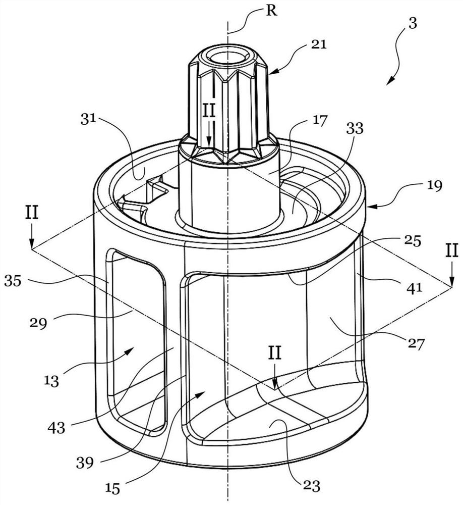
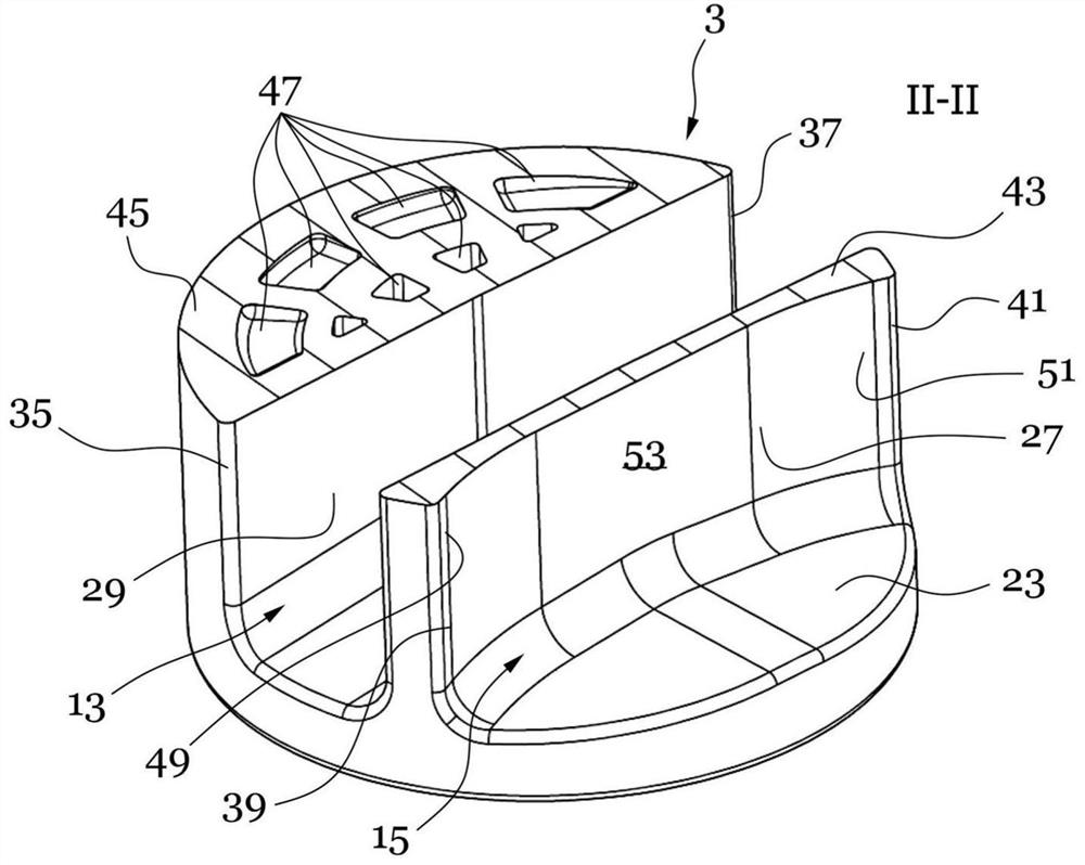
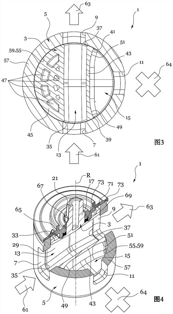
[0035] In the following description of exemplary embodiments of the multiport valve according to the invention and the fluid circuit according to the invention, the multiport valve according to the invention is generally designated with reference numeral 1 , while the fluid circuit according to the invention is generally Reference numeral 100 is provided. according to Figure 1 to Figure 8 The multi-way valve 1 shown in the exemplary embodiment of FIG. 1 is used to control fluid flow in a fluid circuit 100, which may be, for example, a cooling device circuit of a motor vehicle. For example, the multiport valve 1 is preferably produced from plastic by means of a plastic injection molding process. Alternatively, it is conceivable for the multiport valve 1 to be produced, for example, from metal according to known production techniques. Reference basis Figure 1 to Figure 6 An exemplary embodiment of a multiport valve 1 according to the invention is shown. refer to Figure 7...


PUM


Abstract

A multi-way valve for controlling a fluid flow in a fluid circuit, such as a cooling fluid circuit of a motor vehicle, may include a valve housing having at least three fluid connections and a rotary slide for setting the fluid flow. The rotary slide includes at least two fluid channels and is configured to connect two respective fluid connections fluidly via one fluid channel dependent upon its rotary position in relation to its rotational axis. The at least three fluid connections and the at least two fluid channels overlap in relation to a crosswise direction oriented crosswise relative to the rotational axis.

Description

technical field [0001] The invention relates to a multiport valve for controlling a fluid flow in a fluid circuit, in particular a cooling fluid circuit, in particular of a motor vehicle. The invention also relates to a fluid circuit, in particular a cooling fluid circuit, of a motor vehicle having such a multiport valve. Background technique [0002] In the cooling medium circuit of motor vehicles, for example, valves of the multi-way valve type are used, which comprise a housing with a conduit connection for conducting the medium and at least one valve member, which can be used, for example, for conveying the medium Rotary slide valve distributed to different conduit connections. Especially in the increasingly important field of electromobility, the guidance of fluids, in particular cooling fluids, plays an even more decisive role, as does the control of the respective fluid flows with low or no damage. [0003] DE 10014555 A1 discloses a control device for a cooling cir...

Claims


Application Information

Patent Timeline
IPC IPC(8): F16K11/085B60H1/32
CPCF16K11/0856B60H1/32B60H2001/3286F16K11/085F16K11/0853F16K11/076F01P2007/146F01P7/14H02K9/193F16K11/02
Inventor 埃伯哈德·德基厄尔托尔斯滕·霍夫曼马丁·海尔德曼
Owner WOCO INDTECHN
Why Eureka
Try Eureka