Stress wave signal acquisition and analysis method for mechanical equipment

A technology of signal acquisition and analysis method, which is applied in the testing of machines/structural components, force/torque/power measuring instruments, measuring devices, etc. Get the time and priority and other issues to achieve the effect of ensuring normal production work, improving the accuracy and timeliness of maintenance, and ensuring accuracy

Active Publication Date: 2021-04-27
CHONGQING CHUANYI AUTOMATION
View PDF11 Cites 0 Cited by
  • Summary
  • Abstract
  • Description
  • Claims
  • Application Information

AI Technical Summary

Problems solved by technology

However, this monitoring technology can only obtain the frequency components contained in a signal as a whole, but cannot obtain the time and priority of each component, so two signals with a large difference in time domain are likely to get the same spectrum; therefore It is suitable for processing stationary signals, but has certain defects in processing non-stationary signals
However, during the actual operation of mechanical equipment, the signals generated are usually non-stationary signals. Using the existing monitoring technology, the failure can only be reflected after the equipment fails, and the main or prior cause of the failure cannot be judged. Thus affecting the fault location and removal efficiency

Method used


Image

  • Stress wave signal acquisition and analysis method for mechanical equipment
  • Stress wave signal acquisition and analysis method for mechanical equipment
  • Stress wave signal acquisition and analysis method for mechanical equipment

Examples


Embodiment Construction

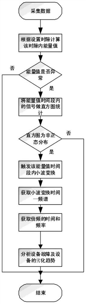
[0032] see Figure 1 to Figure 2 , a stress wave signal acquisition and analysis method for mechanical dynamic equipment, the steps are as follows:

[0033] (1) The stress wave sensor installed at the monitoring point of mechanical equipment sends the stress wave electric signal to the collector, and the stress wave electric signal is a voltage signal.

[0034] (2) The collector performs denoising processing on the received stress wave electrical signal, and adopts a high frequency band filter and a low frequency band filter to perform denoising processing on the stress wave electrical signal, thereby retaining an effective stress wave electrical signal, Make the received stress wave electric signal value more reliable, and obtain x(t) through envelope detection for the stress wave electric signal after denoising processing;

[0035] (3) The collector calculates the stress wave energy value E in the corresponding time slot according to the stress wave electric signal x(t) in ...


PUM


Abstract

The invention discloses a stress wave signal acquisition and analysis method for mechanical moving equipment. The method comprises the following steps that (1) a stress wave sensor sends a stress wave electric signal to an acquirer; (2) the stress wave electric signal is de-noised by the collector, and x(t) is obtained through envelope detection; (3) the collector calculates a stress wave energy value E according to the x (t); (4) the collector compares the stress wave energy value E with an energy threshold value SE, and if SEgt is detected, the collector detects the stress wave energy value E; E, that the stress wave energy value is abnormal is determined; (5) histogram processing is conducted on the abnormal stress wave energy value, if the abnormal stress wave energy value is not in normal distribution, that the equipment has a fault, and triggering continuous wavelet transform is determined; (9) the collector obtains a frequency value of frequency multiplication in the time slot and the time when the frequency value appears according to wavelet transformation, and sends the frequency value and the time to the central control machine; (10) the received frequency multiplication frequency value is matched with a fault expert database by the central control machine, and a fault reason of the equipment is analyzed; and (11) the central control machine stores the received frequency multiplication value and the time value when the frequency multiplication value appears to form a fault degradation trend curve of the mechanical equipment.

Description

technical field [0001] The invention relates to the technical field of fault detection of mechanical dynamic equipment, in particular to a method for collecting and analyzing stress wave signals of mechanical dynamic equipment. Background technique [0002] The current stress wave monitoring technology is to monitor all the energy values ​​emitted by sound such as impact, friction, and cavitation inside the machine as a sign to judge whether the machine has wear or failure. When an abnormal energy value is found, take out the abnormal energy value during this period The collected data, FFT analysis (fast Fourier transform) is performed on these data to obtain the spectrum result, and then the cause of the equipment failure is analyzed by identifying the multiplier value in the spectrum. However, this monitoring technology can only obtain the frequency components contained in a signal as a whole, but cannot obtain the time and priority of the appearance of each component, so ...

Claims


Application Information

Patent Timeline
Patent Type & Authority Applications(China)
IPC IPC(8): G01M99/00G01L5/00
CPCG01M99/00G01L5/00
Inventor 杨露霞钱依祎
Owner CHONGQING CHUANYI AUTOMATION
Why Eureka
Try Eureka