A leakage test system and test method for defective optical device capacitor elements based on the device side

A capacitive element and testing system technology, which is applied in the field of leakage test system for capacitive elements of defective optical devices, can solve problems affecting orders, bad product capacitance testing, customer complaints, etc., and achieve the effects of increasing profits, facilitating mass production, and low cost

Active Publication Date: 2021-06-22
GUILIN OPTOSEAL TECH CO LTD
View PDF8 Cites 0 Cited by
  • Summary
  • Abstract
  • Description
  • Claims
  • Application Information

AI Technical Summary

Problems solved by technology

[0003] 1. The existing scheme for testing capacitors is a test scheme for a single independent capacitor. By charging and discharging the capacitor for direct performance testing, only a single capacitor in an independent state can be tested. It is a direct way to test the capacitor. When the capacitor is assembled with other components Together, existing solutions cannot be tested;
[0004] 2. Optical devices are finished components that have been packaged with capacitors and other chips. At present, there is no way to test defective capacitors at the optical device end, resulting in defective products flowing out to the client, causing customer complaints, and increasing the analysis of defective products by technicians. time and effort, heavily impacting future orders

Method used


Image

  • A leakage test system and test method for defective optical device capacitor elements based on the device side
  • A leakage test system and test method for defective optical device capacitor elements based on the device side
  • A leakage test system and test method for defective optical device capacitor elements based on the device side

Examples


Embodiment Construction

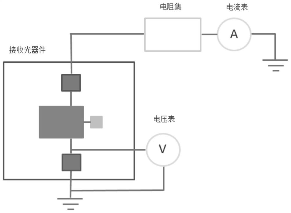
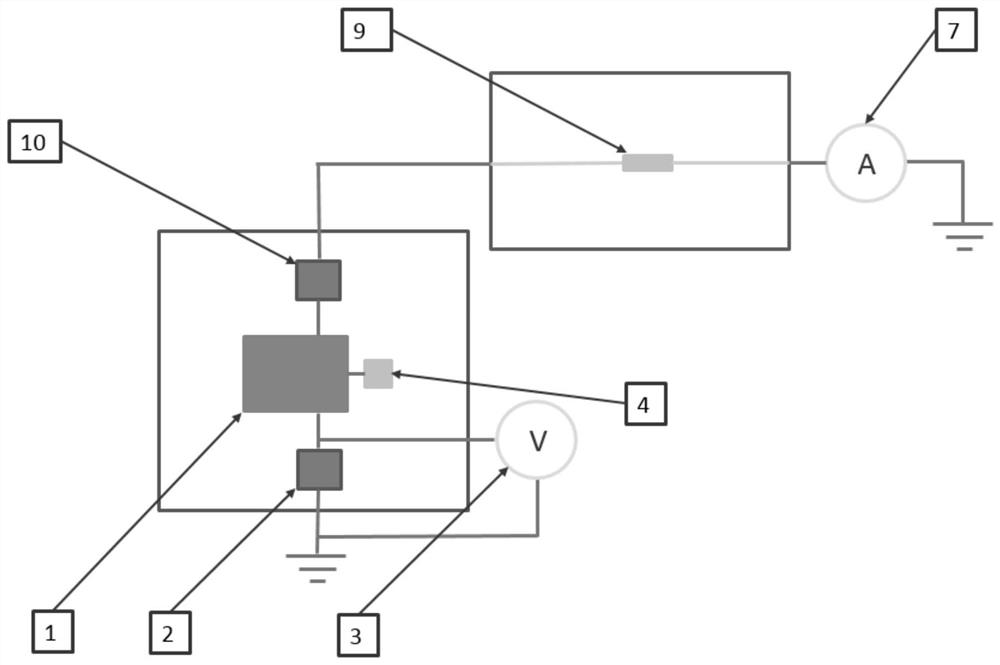
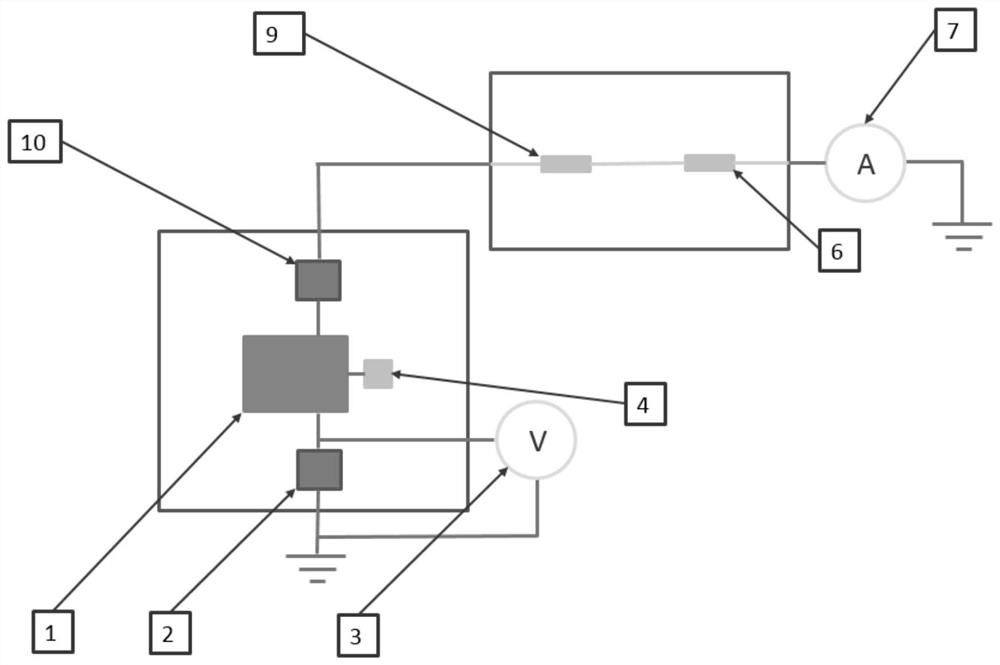
[0042] see figure 1 As shown, the leakage test system of the defective optical device capacitive element based on the device side of the present embodiment includes: a voltmeter 3, an ammeter 7, a variable resistance set and an optical receiving device, wherein the ammeter 7 and one end of the voltmeter 3 are all grounded, and the ammeter The other end of 7 is connected to the variable resistance set, and the other end of the variable resistance set is connected to the receiving optical device, and the receiving optical device includes VCC capacitor 2, transimpedance amplifier 1, RSSI capacitor 10 and detector 4 connected in series, RSSI capacitor 10 One end is connected to the variable resistance set, one end of the VCC capacitor 2 is grounded, the other end is respectively connected to the transimpedance amplifier and the voltmeter 3, and one end of the detector 4 is connected to the transimpedance amplifier 1; the variable resistance set is a series circuit formed by resisto...


PUM


Abstract

The invention provides a leakage test system for defective optical device capacitive elements based on the device end, including: a voltmeter (3), an ammeter (7), a variable resistance set and an optical receiving device, wherein both the ammeter and the voltmeter are grounded, and the ammeter The other end is connected to the variable resistance set, and the other end of the variable resistance set is connected to the optical receiving device. The optical receiving device includes a VCC capacitor (2), a transimpedance amplifier (1), an RSSI capacitor (10) and a detector ( 4), one end of the RSSI capacitor is connected to the variable resistance set, one end of the VCC capacitor is grounded, the other end is respectively connected to the transimpedance amplifier and the voltmeter, and one end of the detector is connected to the transimpedance amplifier; the variable resistance set is a series or parallel connection formed by resistors In the circuit, the resistance of the variable resistor set can be adjusted. Different products have different requirements for matching resistors. By adjusting the voltage value and current value, it is judged whether there is a capacitor failure in the receiving optical device. Corresponding testing methods are also disclosed.

Description

technical field [0001] The invention relates to the field of semiconductor testing, in particular to a leakage testing system and testing method for defective optical device capacitor elements based on the device side. Background technique [0002] With the rapid development of the Internet, big data, artificial intelligence, and high-definition television, the demand for optical fiber network transmission rates is getting higher and higher. Humans use various methods to increase chip transmission rates. With the increase in chip rates, the performance and The process requirements are getting higher and higher, and the process requirements in the product production process are relatively strict, especially in terms of ESD and EOS protection. If relevant measures are not taken well, it is easy to cause damage to chips or components during the production process. Such as figure 1 As shown, the existing test capacitor adopts the direct test method to implement the capacitance ...

Claims


Application Information

Patent Timeline
Patent Type & Authority Patents(China)
IPC IPC(8): G01R31/26G01R31/52
CPCG01R31/2601G01R31/52
Inventor 屈显波黄祥恩
Owner GUILIN OPTOSEAL TECH CO LTD
Why Eureka
Try Eureka