Road bayonet vehicle position detection method

A detection method and vehicle technology, applied in the direction of neural learning methods, instruments, biological neural network models, etc., can solve problems such as the influence of traffic efficiency, failure to trigger verification tasks, missed detection, etc.

Pending Publication Date: 2021-04-27
CHINACCS INFORMATION IND
View PDF1 Cites 0 Cited by
  • Summary
  • Abstract
  • Description
  • Claims
  • Application Information

AI Technical Summary

Problems solved by technology

[0009] Q5: The vehicle capture machine has a small probability of missed capture due to the capture line drawing problem, light problem and other reasons. At this time, the verification task cannot be triggered and a certain amount of manual intervention is required.
[0010] Q6: The best captur

Method used


Image

  • Road bayonet vehicle position detection method
  • Road bayonet vehicle position detection method
  • Road bayonet vehicle position detection method

Examples


Embodiment 1

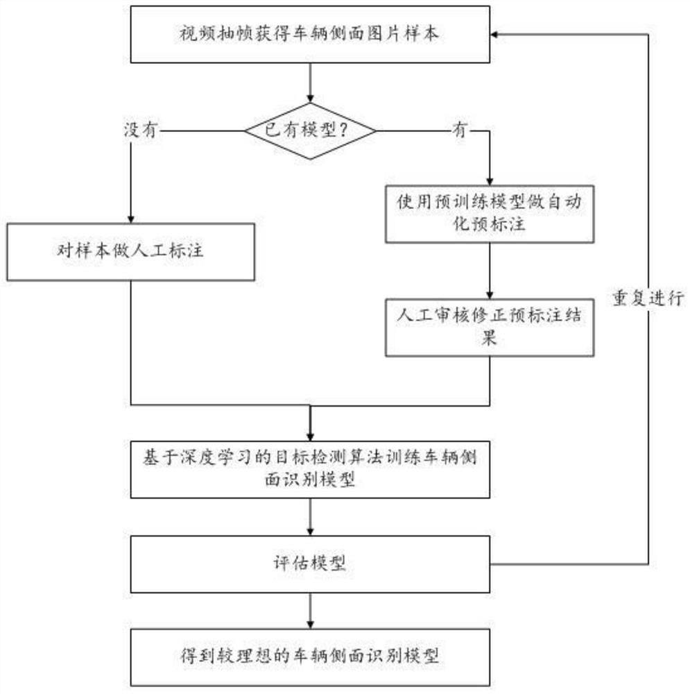
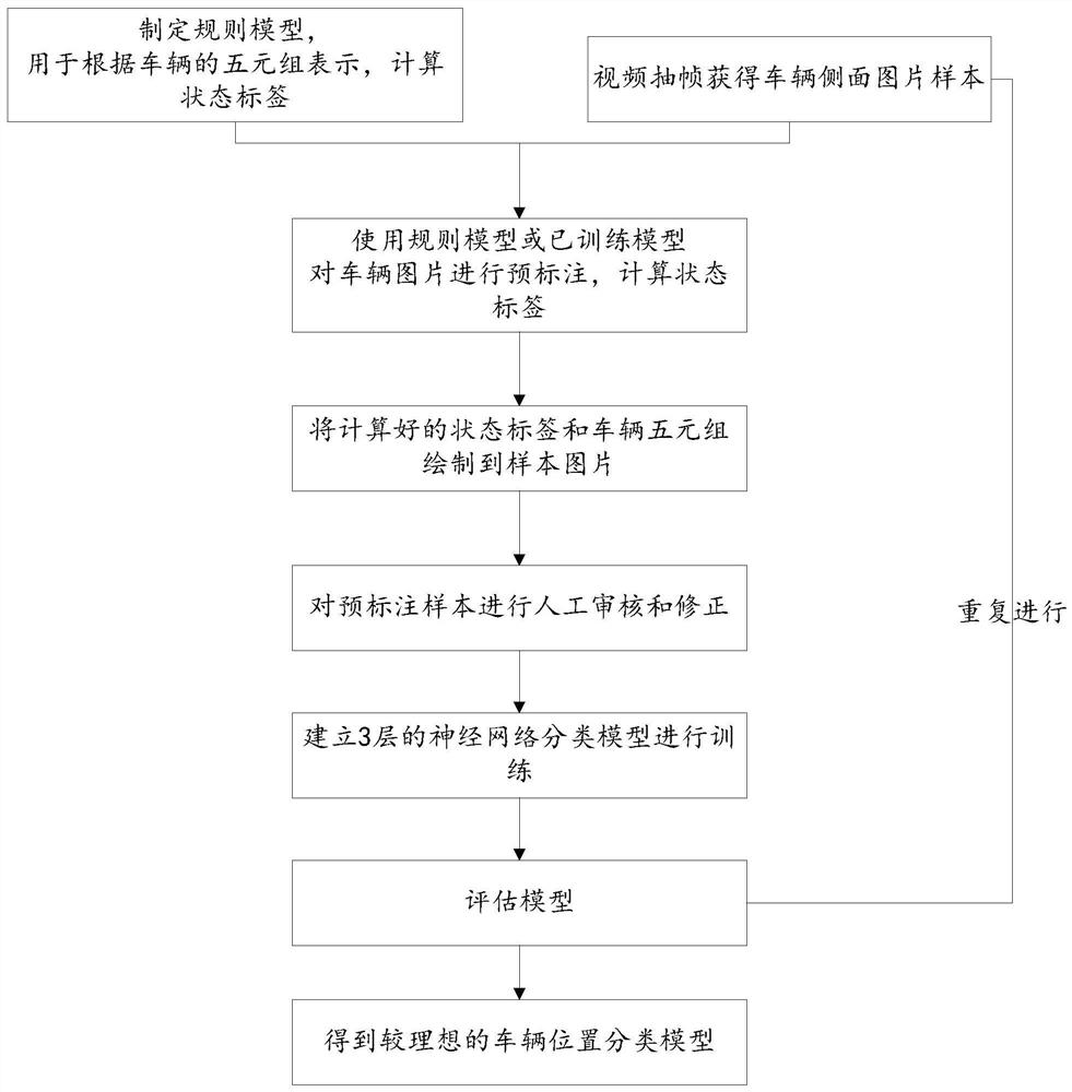
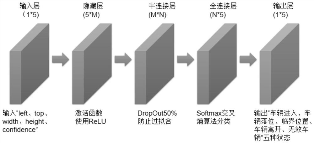
[0080] see Figure 1 to Figure 5 , the present invention provides a vehicle position detection method at a road bayonet, which uses a target detection algorithm based on deep learning to carry out targeted training on vehicle side pictures to obtain a vehicle side recognition model, and cooperates with a camera installed on the side of the verification area (generally Use the left rear camera) to accurately identify the coordinate position of the vehicle in the screen in real time in the video, which can be represented by a quintuple (left, top, width, height, confidence), which are the x coordinates of the vehicle rectangle on the left side of the screen, Top y-coordinate, width, height and confidence. The training process of the vehicle side recognition model, such as figure 1 The training flow chart of the vehicle side recognition model is shown as follows: firstly, the vehicle side image sample is obtained by sampling video frames; the samples are manually marked or the p...

Embodiment 2

[0103] see Image 6 , taking the implementation of the trolley lane as an example:

[0104] Step 1: If Image 6 As shown in the schematic diagram of the installation and deployment of the trolley lane, install the front-end equipment:

[0105] Plan the lane range and the verification waiting area according to the standard lane width. A vehicle capture camera 3 is installed right in front of the driveway. A set of boxes are installed on both sides of the lane waiting area, and 4 face capture cameras 4 are respectively installed in the box. According to the relative position with the vehicle, they are respectively front left, rear left, front right, and rear right cameras. The functions of each device are as follows:

[0106] 1) Vehicle capture camera 3: capture vehicle photos and analyze the license plate. In this method, use a capture machine that supports the active capture SDK interface.

[0107] 2) 4 face capture cameras 4: Synchronously collect the video of the driver ...


PUM


Abstract

The invention discloses a road bayonet vehicle position detection method, which relates to the technical field of security check, and adopts the technical scheme: acquiring a vehicle video through a camera located at the side part of a vehicle; performing frame extraction on the acquired video to obtain a vehicle side picture, and performing unified processing on the picture; recognizing the position of the vehicle through the obtained picture by using a vehicle side recognition model; and classifying vehicle position states by using a vehicle position classification model. The beneficial effects of the invention are that the method achieves the more accurate detection of the position of a vehicle at a road gate through combining the vehicle side recognition model and the vehicle position classification model, and is higher in automation degree of a verification task. In addition, under various scenes, vehicle departure can be accurately found, and better fault tolerance is achieved. A better triggering mechanism is provided for allocating a verification task to the vehicle in combination with the existing vehicle verification area.

Description

technical field [0001] The invention relates to the technical field of security inspection, in particular to a vehicle position detection method at a road checkpoint. Background technique [0002] In our company's patent "CN202010159007-A Mixed Verification System and Method for People and Vehicles at Intelligent Checkpoints", a mixed verification system and method for people and vehicles at intelligent checkpoints have been described, hereinafter referred to as the original verification method. [0003] In this method, the position sensor and the relay signal are used to determine whether the vehicle has reached the proper position. But this approach has some limitations, as described below: [0004] Q1: It can only detect whether the vehicle is seated and whether the vehicle has left. It cannot be detected immediately when the vehicle starts to enter the verification area, nor can it accurately identify the current position of the vehicle; [0005] Q2: The positioning se...

Claims


Application Information

Patent Timeline
IPC IPC(8): G06K9/00G06K9/62G06N3/04G06N3/08
CPCG06N3/08G06V20/20G06N3/045G06F18/2414
Inventor 魏晟坤尚志强朱洁
Owner CHINACCS INFORMATION IND
Why Eureka
Try Eureka