Digital alloy and digital alloy medium wave infrared detector

An infrared detector, digital technology, used in semiconductor devices, electrical components, nanotechnology, etc., can solve problems such as reducing quantum efficiency

Active Publication Date: 2021-04-27
苏州焜原光电有限公司
View PDF7 Cites 0 Cited by
  • Summary
  • Abstract
  • Description
  • Claims
  • Application Information

AI Technical Summary

Problems solved by technology

[0006] The purpose of the present invention is to solve the problem that there is a higher valence band order in the absorbing layer and the barrier layer in the existing barrier device, so that the holes are hindered by the valence barrier during the movement, and the quantum efficiency is reduced. Insufficient, provide a digital alloy AlAsSb material and a digital alloy mid-wave infrared detector

Method used


Image

  • Digital alloy and digital alloy medium wave infrared detector
  • Digital alloy and digital alloy medium wave infrared detector
  • Digital alloy and digital alloy medium wave infrared detector

Examples


Embodiment 1

[0101] The preparation method of the infrared device of the present invention: the steps include:

[0102] 1. Load the GaSb substrate into the growth chamber of the MBE system;

[0103] 2. When the vacuum in the growth chamber is better than 1E-6 torr, heat the substrate to 500-700 °C to remove the residual oxide layer on the substrate surface;

[0104] 3. Lower the deoxidation temperature by 10-200°C, and grow a GaSb buffer layer with a thickness of 100-1000 nm;

[0105] 4. On the basis of the buffer layer, grow a layer of heavily doped blk-InAsSb layer with a thickness of 50-1000 nm as the n-type electrode of the detector;

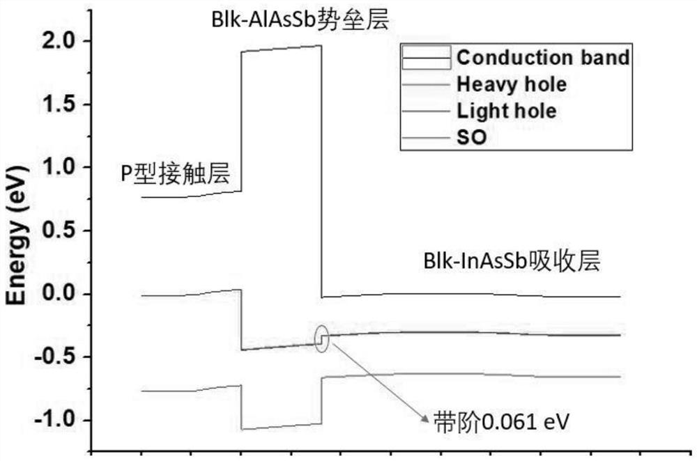
[0106] 5. Grow a layer of non-doped blk-InAsSb with a thickness of 500-10000 nm as the absorbing layer of the detector;

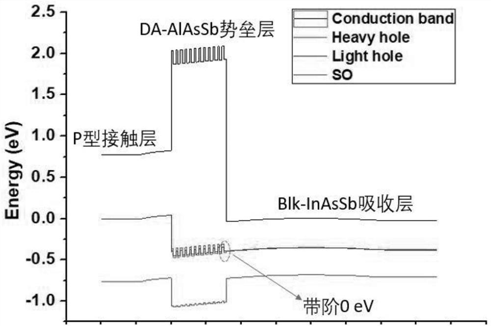
[0107] 6. Grow a layer of AlSb material with a thickness of d1, and then grow a layer of AlAsxSb1-x material with a thickness of d2 to form a basic unit with a thickness of d1+d2 to obtain DA-AlAsySb1-y. The average As composition ...

Embodiment 2

[0114] The preparation method of the infrared device of the present invention: the steps include:

[0115] 1. Load the GaSb substrate into the growth chamber of the MBE system;

[0116] 2. When the vacuum in the growth chamber is better than 1E-6 torr, heat the substrate to 500-700 °C to remove the residual oxide layer on the substrate surface;

[0117] 3. Lower the deoxidation temperature by 10-200°C, and grow a GaSb buffer layer with a thickness of 100-1000 nm;

[0118] 4. On the basis of the buffer layer, grow a layer of heavily doped blk-InAsSb layer with a thickness of 50-1000 nm as the n-type electrode of the detector;

[0119] 5. Grow a layer of p-type lightly doped blk-InAsSb with a thickness of 500-10000 nm as the absorber layer of the detector, the dopant is Be, and the p-type concentration range: 1E+15-5E+16 / cm3;

[0120] 6. Grow a layer of AlSb material with a thickness of d1, and then grow a layer of AlAsxSb1-x material with a thickness of d2 to form a basic uni...

Embodiment 3

[0127] The preparation method of the infrared device of the present invention: the steps include:

[0128] 1. Load the GaSb substrate into the growth chamber of the MBE system;

[0129] 2. When the vacuum in the growth chamber is better than 1E-6 torr, heat the substrate to 500-700 °C to remove the residual oxide layer on the substrate surface;

[0130] 3. Lower the deoxidation temperature by 10-200°C, and grow a p-type heavily doped material with a thickness of 50-1000 nm as the p-type electrode layer;

[0131] 4. Grow a layer of AlSb material with a thickness of d1, and then grow a layer of AlAsxSb1-x material with a thickness of d2 to form a basic unit with a thickness of d1+d2 to obtain AlAsySb1-y. The average As composition in this digital alloy is represented by y express. The relationship between the overall average As composition y in the digital alloy and the As composition x in one layer of the basic unit is expressed as follows,

[0132] The satisfaction of thi...


PUM

PropertyMeasurementUnit
Thicknessaaaaaaaaaa
Thicknessaaaaaaaaaa
Thicknessaaaaaaaaaa

Abstract

The invention provides a digital alloy AlAsSb material and a digital alloy medium-wave infrared detector, and aims to overcome the defects that an absorption layer and a barrier layer of an existing barrier type device have a relatively high valence band order, holes are blocked by valence band barriers in the moving process, and quantum efficiency is reduced, and provides the digital alloy AlAsSb material and the digital alloy medium-wave infrared detector; a layer of AlAsxSb1-x material with the thickness of d2 grows to form an AlAsySb1-y basic unit with the thickness of d1+d2, d1+d2 is taken as a period, repeated growth for n periods is achieved to form the digital alloy DA-AAlAsySb1-y, y is the overall average As component in the digital alloy, and x is the As component in one layer of the basic unit, by adopting the digital alloy and the digital alloy medium-wave infrared detector provided by the invention, hole movement is smoother, quantum efficiency of the detector can be effectively improved, and the dark current of the device is not influenced, so the detector can be more easily adapted to different absorption layers.

Description

technical field [0001] The invention relates to a digital alloy material and a mid-wave infrared detector with the digital alloy material. Background technique [0002] The mid-wave infrared detector with a detection wavelength of 3-5 microns is widely used in aerospace, satellite reconnaissance, precision guidance, night vision imaging and other fields. The current mainstream InSb and HgCdTe-based mid-wave infrared detectors have excellent performance, but they need to work in a low-temperature environment of about 80 K, so the requirements for the refrigerator are very high, which makes the overall size and weight of the detector large, and the power consumption is low. high cost. Reducing the size, weight, power consumption, cost, and improving reliability of detectors is an important development trend of detectors. The reduction of size, weight, power consumption, cost and improvement of reliability of detectors can greatly expand its The scope of application, for exam...

Claims


Application Information

Patent Timeline
IPC IPC(8): H01L31/0352H01L31/0304H01L31/109B82Y30/00B82Y40/00
CPCH01L31/03529H01L31/03042H01L31/03046H01L31/109B82Y30/00B82Y40/00
Inventor 陈意桥张国祯陈超周浩
Owner 苏州焜原光电有限公司
Why Eureka
Try Eureka