
Tool inclination angle gravity compensation method

A technology of gravity compensation and gravity direction, which is applied in the direction of manufacturing tools, metal processing equipment, workpiece feed movement control, etc., can solve the problems of measurement accuracy and response speed limitation, signal distortion, contact force fluctuation, etc., and achieve anti-interference ability Strong, high measurement accuracy, constant contact force effect

Pending Publication Date: 2021-04-30
廊坊市亿创科技有限公司
View PDF6 Cites 1 Cited by
  • Summary
  • Abstract
  • Description
  • Claims
  • Application Information

AI Technical Summary

Problems solved by technology

This component force will cause fluctuations in the contact force, resulting in uneven processing, burrs and other processing defects
[0003] At present, most of the robot grinding constant force control mainly use inclination sensor in the aspect of tool inclination measurement, and the measurement accuracy and response speed are limited by the performance of the sensor.
The output signal of the sensor is generally an analog quantity. During the transmission process, the signal is easily distorted by the interference of the on-site electromagnetic field, which affects the grinding effect.

Method used


Image

  • Tool inclination angle gravity compensation method
  • Tool inclination angle gravity compensation method
  • Tool inclination angle gravity compensation method

Examples


Embodiment Construction

[0034] The present invention will be described in detail below with reference to the accompanying drawings and examples. Each example is provided by way of explanation of the invention, not limitation of the invention. In fact, those skilled in the art will recognize that modifications and variations can be made in the present invention without departing from the scope or spirit of the invention. For example, features illustrated or described as part of one embodiment can be used on another embodiment to yield a still further embodiment. Therefore, it is intended that the present invention includes such modifications and variations as come within the scope of the appended claims and their equivalents.

[0035] In the description of the present invention, the terms "longitudinal", "transverse", "upper", "lower", "front", "rear", "left", "right", "vertical", "horizontal", " The orientations or positional relationships indicated by "top", "bottom", etc. are based on the orienta...


PUM


Abstract

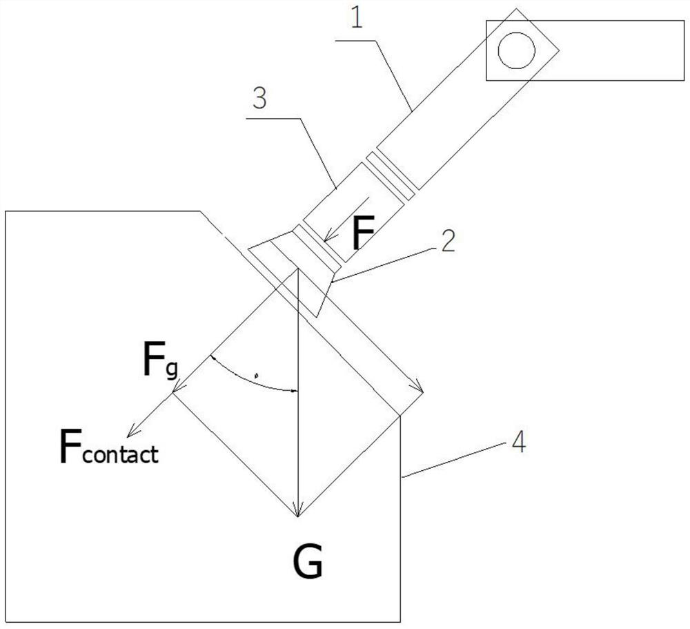
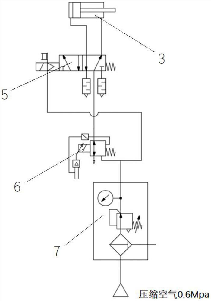
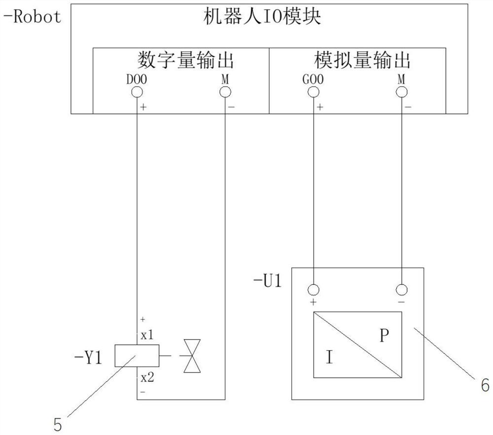
The invention provides a tool inclination angle gravity compensation method. A tool is grabbed through driving equipment. The method comprises the steps that the axial direction of the tool is obtained, and an included angle between the axial direction of the tool and the gravity direction is calculated; the gravity of the tool is calculated according to the mass of the tool, and the component force of the gravity of the tool in the axial direction of the tool is calculated based on the included angle; and the tool has a contact force preset value, the output force which should be given to the tool by the driving equipment is calculated according to the contact force preset value and the component force of the gravity of the tool in the axial direction of the tool, and constant control over the contact force when the tool is subjected to polishing and grinding operation is achieved. According to the method, the inclination angle of the tool is calculated through a robot, influence of tool gravity and tool space posture on the contact force is corrected in real time, constant contact force in the machining process is guaranteed, and the method has the characteristics of being high in measurement precision, short in response time and high in anti-jamming capability. Control over the non-axial force can also be subjected to extension calculation by this method.

Description

technical field [0001] The invention relates to the technical field of robot control, in particular to a tool inclination angle gravity compensation method. Background technique [0002] When the robot grasps the tool for polishing and grinding operations, if the posture of the robot grasping the tool changes, the component force of the tool gravity along the tool axis will also change. This component force will cause fluctuations in the contact force, which in turn will cause processing defects such as uneven processing and burrs. [0003] At present, most of the robot grinding constant force control mainly use inclination sensors in the measurement of tool inclination angle, and the measurement accuracy and response speed are limited by the performance of the sensor. The output signal of the sensor is generally an analog quantity. During the transmission process, the signal is easily distorted by the interference of the on-site electromagnetic field, which affects the gri...

Claims


Application Information

Patent Timeline
Patent Type & Authority Applications(China)
IPC IPC(8): B25J9/16B25J11/00B24B49/00
CPCB24B49/00B25J9/16B25J9/1679B25J11/0065
Inventor 崔洪亮马瑞兵郭延青李超夏武强孙朋非李天伟
Owner 廊坊市亿创科技有限公司
Learn More