
Eureka
For R&D, Eureka makes reading and utilizing patents & technical documents easy.
Eureka AIR
Designed for self-driven R&D workflows. Generate viable solutions, solve complex R&D challenges, empower your innovation with AI.

Eureka Materials
Designed for material experts only. Revolutionize your material R&D, from search, analyze, to developing new materials.

TechResearch
Generate reliable direction feasibility study reports for your R&D in just a few steps.

TechSeek
Discover and master advanced knowledge NOW. Basics, ideas, possibilities, all at once.

TechMind
As an expert in R&D Theories, TechMind can generates customized viable solutions instantly.

TechRisk
Analyze your overall solution with one click, know your potential R&D risks in advance.

TechMonitor
Get weekly tech updates, stay abreast of the latest tech innovations and key insights.
Power battery protection plate and power battery protection system
A power battery and protection board technology, applied in battery circuit devices, safety/protection circuits, emergency protection circuit devices, etc., can solve problems such as high cost and complex hardware structure
- Summary
- Abstract
- Description
- Claims
- Application Information
AI Technical Summary
Problems solved by technology
Method used
Image

Examples
Embodiment 1
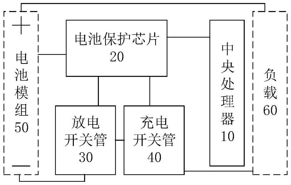
[0028] figure 1 A schematic structural diagram of a power battery protection board provided for an embodiment of the present invention, as shown in figure 1 As shown, the power battery protection board includes: a central processing unit 10 , a battery protection chip 20 , a discharge switch tube 30 and a charge switch tube 40 .
[0029] The central processing unit 10 is connected with the battery protection chip 20; the battery protection chip 20 is also respectively connected with the state detection terminal of the battery module 50, the first end of the discharge switch tube 30 and the first end of the charge switch tube 40; the discharge switch The second end of the tube 30 is connected to the negative pole of the battery module 50, the third end of the discharge switch tube 30 is connected to the second end of the charge switch tube 40, and the third end of the charge switch tube 40 is connected to the first end of the load 60. The positive terminal of the battery modul...
Embodiment 2
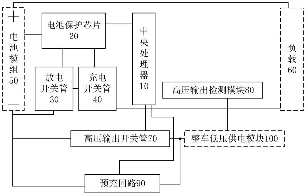
[0090] The embodiment of the present invention also provides a power battery protection system. The power battery protection system includes any power battery protection board in the first embodiment above, and further includes: a battery module 50 and a vehicle low-voltage power supply module 100 .
[0091] The power battery protection board is respectively connected with the battery module 50 and the vehicle low-voltage power supply module 100 .
[0092] The vehicle low-voltage power supply module 100 is used to step down the voltage output by the power battery protection board to provide low-voltage working power for the vehicle.
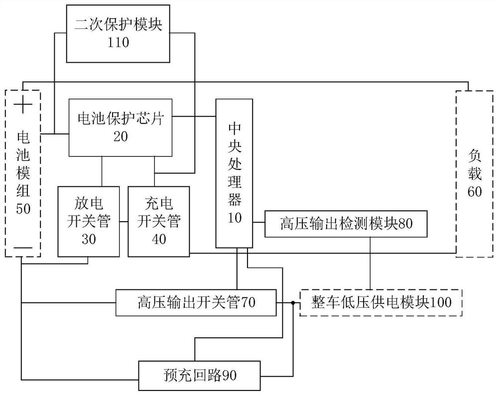
[0093] It should be noted that like numerals and letters denote similar items in the following figures, therefore, once an item is defined in one figure, it does not require further definition and explanation in subsequent figures.
PUM
 Abstract
Description
Claims
Application Information
 - R&D Engineer
- R&D Manager
- IP Professional
- Industry Leading Data Capabilities
- Powerful AI technology
- Patent DNA Extraction
Browse by: Latest US Patents, China's latest patents, Technical Efficacy Thesaurus, Application Domain, Technology Topic, Popular Technical Reports.
© 2024 PatSnap. All rights reserved.Legal|Privacy policy|Modern Slavery Act Transparency Statement|Sitemap|About US| Contact US: help@patsnap.com