
Textile yarn guide device with improved clamping friction and adjustable clamping force

A yarn guide device and friction technology, applied in the textile field, can solve problems such as easy yarn breakage, inconvenient handling of textile products, troublesome operation, etc., and achieve the effect of removing yarn dust

Inactive Publication Date: 2021-04-30
温州培堡尼服装有限公司
View PDF0 Cites 0 Cited by
  • Summary
  • Abstract
  • Description
  • Claims
  • Application Information

AI Technical Summary

Problems solved by technology

[0004] The purpose of the present invention is: in order to solve the problem that the yarn guide device in the prior art generally uses the roller to control the yarn to adjust its tension, but the existing adjustment method is troublesome to operate, and the rollers at different positions may not be able to achieve accurate unity The standard affects the clamping strength of the roller to the yarn, causing the yarn to be easily broken or unable to be straightened during the yarn guiding process, which affects the normal processing of the yarn. At the same time, the existing yarn guiding device handles the yarn, and the yarn If there is a lot of dust in the textile product, if it is not cleaned in time, there will be a large amount of dust in the textile product, which will bring some inconvenience to the subsequent processing of the textile product. The proposed textile guide yarn with improved clamping friction and adjustable clamping force device

Method used


Image

  • Textile yarn guide device with improved clamping friction and adjustable clamping force
  • Textile yarn guide device with improved clamping friction and adjustable clamping force
  • Textile yarn guide device with improved clamping friction and adjustable clamping force

Examples


Embodiment Construction

[0034] The following will clearly and completely describe the technical solutions in the embodiments of the present invention with reference to the accompanying drawings in the embodiments of the present invention. Obviously, the described embodiments are only some, not all, embodiments of the present invention. Based on the embodiments of the present invention, all other embodiments obtained by persons of ordinary skill in the art without creative efforts fall within the protection scope of the present invention.

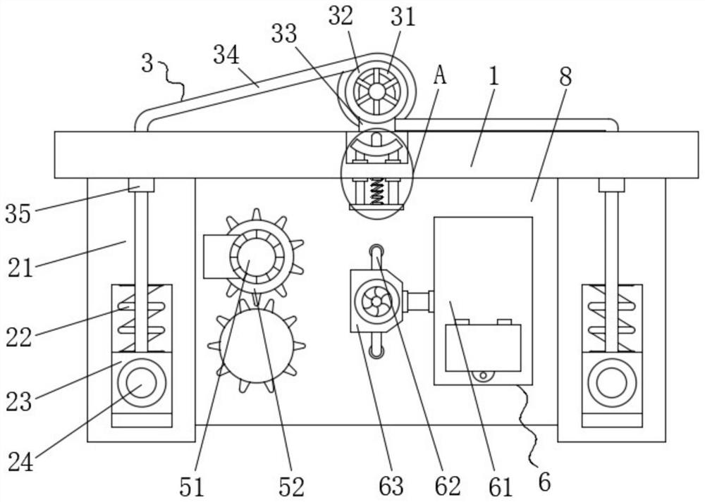
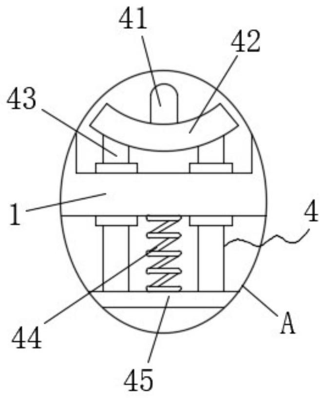
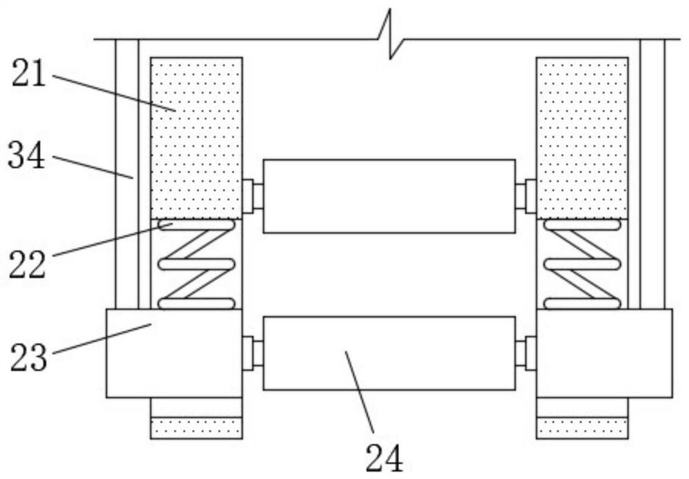
[0035] see Figure 1-7 , the present invention provides a technical solution: a textile yarn guide device with improved clamping friction and adjustable clamping force, comprising a top plate 1, clamping mechanisms 2 are provided on the left and right sides of the lower surface of the top plate 1, two A fixed shell 8 is fixedly connected between the clamping mechanisms 2, a cleaning mechanism 5 and a dust suction mechanism 6 are arranged in the fixed casing 8, a fl...


PUM


Abstract

The invention discloses a textile yarn guide device with improved clamping friction and adjustable clamping force, and belongs to the technical field of textile. The textile yarn guide device comprises a top plate, clamping mechanisms are arranged on the left side and the right side of the lower surface of the top plate, a fixed shell is fixedly connected between the two clamping mechanisms, and a cleaning mechanism and a dust suction mechanism are arranged in the fixed shell. According to the textile yarn guide device provided by the invention, the clamping mechanisms are arranged, two yarns pass through the space between two extrusion rollers and can be clamped by extrusion rollers, the effect of conveniently guiding the straightened yarns is achieved, and the extrusion roller on the lower side can move upwards under the action of a limiting block and a limiting hole; a second spring can contract through self elasticity to pull a pull plate to move upwards, the pull plate drives an arc-shaped plate to move upwards through a sliding rod, the arc-shaped plate drives a contact pin to move upwards to be inserted into a slot, the pull plate is pulled to move downwards to drive the contact pin to be separated from the slot, and a hand wheel is not fixed any more and can be adjusted at will; and meanwhile, the contact pin can be inserted into any slot to achieve a fixing effect.

Description

technical field [0001] The invention belongs to the technical field of textiles, and in particular relates to a textile yarn guide device with improved clamping friction and adjustable clamping force. Background technique [0002] The original meaning of textile is taken from the general term of spinning and weaving, but with the continuous development and improvement of the textile knowledge system and subject system, especially after the emergence of non-woven textile materials and three-dimensional composite weaving technologies, textile is not only the traditional spinning and weaving Weaving also includes non-woven technology, three-dimensional weaving technology, electrostatic nano-netting technology, etc. Weaving is roughly divided into two processes: spinning and weaving. According to legend, the origin of Chinese textiles began with Leizu raising silkworms and smelting silk. Archaeologists discovered bone needles on the archaeological sites of cavemen in the Paleol...

Claims


Application Information

Patent Timeline
IPC IPC(8): B65H75/44B65H59/28B65H51/08B08B9/093B08B5/04B08B1/04B08B1/02B08B1/00
CPCB65H75/4492B65H75/44B65H59/28B65H51/08B08B5/04B08B9/0936B08B1/20B08B1/143B08B1/32
Inventor 邱燕邱元锋
Owner 温州培堡尼服装有限公司
Learn More