A guiding device and method suitable for draining turbidity and storing clear water source reservoirs

A technology for guiding devices and reservoirs, which is applied in measuring devices, water conservancy projects, and water conservancy engineering equipment. It can solve problems such as diving into the bottom of the reservoir, rising turbidity, and pollution of the bottom water body, so as to improve the efficiency of turbidity removal, prolong the service life, Efficient turbidity removal effect

Active Publication Date: 2022-06-24
YANCHENG INST OF TECH +1
View PDF0 Cites 0 Cited by
  • Summary
  • Abstract
  • Description
  • Claims
  • Application Information

AI Technical Summary

Problems solved by technology

Surface flow is the hyperpycnal flow floating on the surface of the reservoir. This kind of hyperpycnal flow will not infiltrate or submerge to a lesser extent, and will first pollute the surface of the reservoir; when the bottom is undercurrent, the hyperpycnal flow will directly submerge into the bottom of the reservoir, causing the bottom Water pollution; interlaminar flow runs along the bottom of the reservoir upstream, but after reaching a certain depth, it will separate from the bottom of the reservoir and continue to move forward along a certain depth level, resulting in an increase in the turbidity of the middle water layer
[0004] Different manifestations of hyperpycnal flow will cause the turbidity of different water layers of the reservoir to rise. The traditional flood season flood discharge scheme generally considers the reservoir water level. When the reservoir water level rises to the flood limit level, the flood discharge begins. The current flood discharge is basically based on Water quantity is considered, but water quality-water quantity linkage is not considered

Method used


Image

  • A guiding device and method suitable for draining turbidity and storing clear water source reservoirs
  • A guiding device and method suitable for draining turbidity and storing clear water source reservoirs
  • A guiding device and method suitable for draining turbidity and storing clear water source reservoirs

Examples


Embodiment Construction

[0030] The technical solutions provided by the present invention are further described below in conjunction with the embodiments. The specific embodiment takes a large water depth layered water source reservoir in the northwest as an example to illustrate the technical solution of the invention.

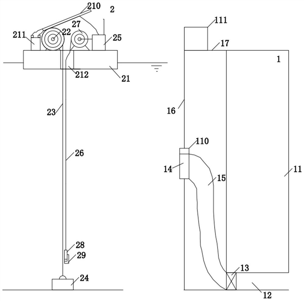
[0031] The invention provides a guiding device suitable for discharging turbidity and storing clear water in a water source reservoir. The guiding device is mainly composed of a movable flood discharge unit 1 , a guiding unit 2 for discharging turbidity and clearing storage, and an operation terminal 3 .

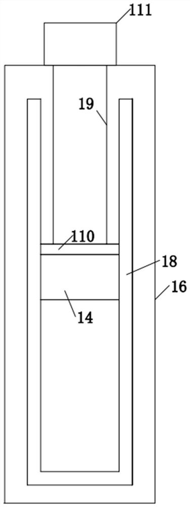
[0032] like figure 1 As shown, the movable flood discharge unit 1 is mainly composed of a dam body 11, a flood discharge tunnel 12, a regulating gate 13, a movable flood discharge head 14 and a connecting pipeline 15 and the like. There is a flood discharge tunnel 12 under the dam, and a regulating gate 13 is arranged on the flood discharge tunnel to adjust the flood discharge vo...


PUM


Abstract

A guiding device and method applicable to the discharge and storage of turbidity and clear water in water source reservoirs according to the present invention includes a movable flood discharge unit, a guide unit for turbid discharge and clear storage, and an operation terminal; There is a movable flood discharge head in the rail, and a hoist is arranged above the slide rail. The movable flood discharge head communicates with the adjustment gate at the bottom of the dam body through a connecting pipeline; An integrated host is provided, and a measuring probe is connected to the integrated host, and an electric winch is arranged on the floating body, and the measuring cable is wound in the electric winch. The invention can detect the submerged position of the flood peak of the hyperpycnal flow in real time. When the flood discharge is required, the operation management personnel can accurately move the movable flood discharge head to the height of the flood peak, efficiently drain the high-turbidity water body, realize the turbidity storage of the water source reservoir, and prolong the life of the flood. reservoir life.

Description

technical field [0001] The invention belongs to the technical field of water environmental protection, and in particular relates to a guiding device and method suitable for discharging turbidity and storing clear water in water source reservoirs. Background technique [0002] The rainstorm runoff during the flood season will have a significant impact on the water quality and hydraulic state of the reservoir. In many lakes and reservoirs, the sedimentation of the reservoir and the increase of the effluent turbidity are often accompanied by the rainstorm after the rainstorm. Changes in temperature difference and sediment content of rainstorm runoff will cause changes in the density of inflow runoff. When the rainstorm runoff moves to the reservoir, it will dive into the water layer with the same density and produce a hyperpycnal flow. [0003] There are three main movement forms of hyperpycnal flow in stratified reservoirs, namely surface flow, interlayer flow and bottom subsu...

Claims


Application Information

Patent Timeline
Patent Type & Authority Patents(China)
IPC IPC(8): E02B1/00E02B8/04G01D21/02
CPCE02B1/003E02B8/045G01D21/02
Inventor 马卫星丁成李璇李朝霞潘梅郭庆园
Owner YANCHENG INST OF TECH
Why Eureka
Try Eureka