
Double-groove hedging energy dissipation method and spillway thereof

A spillway and energy dissipation technology, applied in water conservancy projects, sea area projects, coastline protection, etc., can solve the problems of large project investment, waste of stone excavation costs, and difficult construction of high slopes, so as to reduce project investment, The effect of reducing the amount of energy dissipation works and reducing the potential energy of floods

Inactive Publication Date: 2021-04-30
CHINA POWER CONSRTUCTION GRP GUIYANG SURVEY & DESIGN INST CO LTD
View PDF4 Cites 0 Cited by
  • Summary
  • Abstract
  • Description
  • Claims
  • Application Information

AI Technical Summary

Problems solved by technology

Due to the steep slope and the strict requirements on the foundation conditions of the discharge channel, a large amount of stonework needs to be excavated inside the discharge channel to meet the foundation conditions of the external discharge channel, which not only wastes the excavation cost of stonework, but also easily forms a high side on the inside Slope, the project investment is large, and the construction of high slope is difficult

Method used


Image

  • Double-groove hedging energy dissipation method and spillway thereof

Examples


Embodiment Construction

[0017] The present invention will be further described in detail below in conjunction with the accompanying drawings and embodiments.

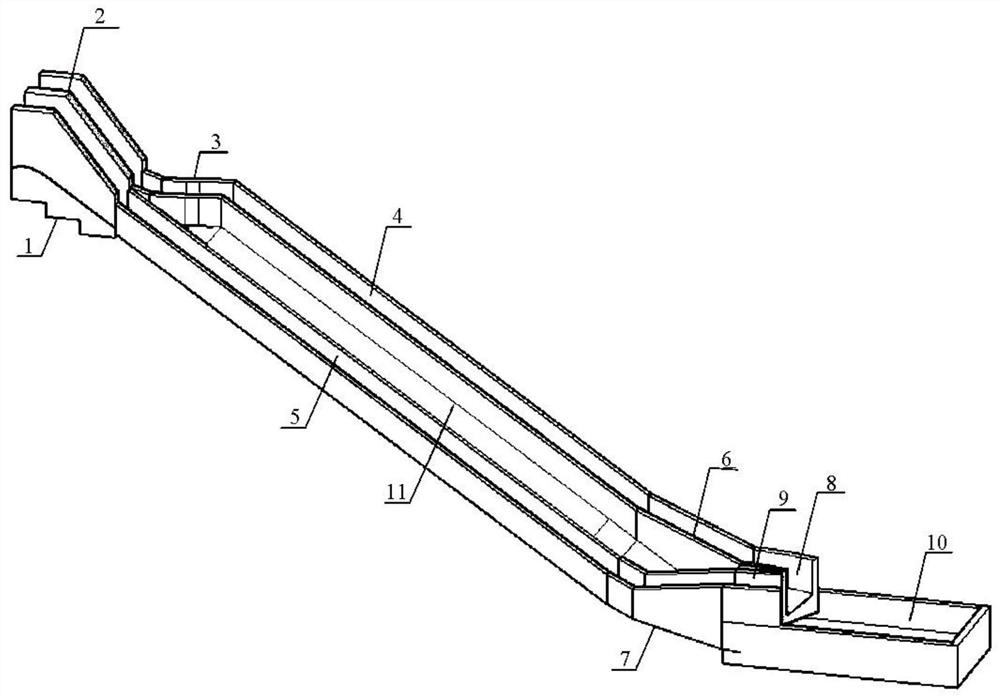
[0018] Such as figure 1 As shown, the double-groove hedging energy dissipation spillway of the present invention mainly includes the following parts: overflow weir 1, gate pier 2, turning gradual change section 1 3, high side discharge chute 4, low side discharge chute 5, turning gradual change section 2 6, Turning transition section 3 7, down discharge port 8, up pick port 9, apron 10, side slope 11 between two-stage chute, etc.

[0019] Spillway overflow weir 1 and gate pier 2 are the main structures of conventional spillways. The key of the present invention is that the high side discharge channel 4 is set at the top of the low side discharge channel 5 through the setting of the turning gradient section-3, at the near end of the double channel. , and through the setting of the turning transition section two 6 and the turning transition sec...


PUM


Abstract

The invention discloses a double-groove hedging energy dissipation method and a spillway thereof. According to the double-groove hedging energy dissipation method, water flow is subjected to hydraulic adjustment under the action of water flow gravity through the structural arrangement of a left-level discharge chute, a right-level discharge chute and a high-level discharge chute, and the hedging energy dissipation effect is achieved above the tail part of the discharge chutes; the spillway is provided with left and right high and low discharge chutes, that is, a high-side discharge chute and a low-side discharge chute, meanwhile, the overflow weir is divided into left and right gate holes by gate piers, the gate piers extend to the bottom of the overflow weir, at the bottom of the overflow weir, a bottom plate of the high-side discharge chute is lifted through a turning transition section, the high-side discharge chute is higher than the low-side discharge chute, and after passing through a turning transition section, the high-side discharge chute and the low-side discharge chute pass through the turning transition section. The double discharge chutes are arranged at the same slope ratio; when approaching the tail part of the discharge chute, the double discharge chute adjusts the water flow direction through the gradually-changed turning section again, and the water flow is subjected to hedging energy dissipation again by changing the arrangement mode of the bottom plate and the two side walls of the discharge chute at the tail end of the discharge chute, so that the situation that the high-speed water flow is directly converging into a stilling pool is prevented, and the structure of an energy dissipater can be effectively optimized.

Description

technical field [0001] The technical field of the invention relates to water conservancy and hydropower fixed buildings, and in particular to a bank spillway of a water conservancy project. Background technique [0002] The spillway is a discharge structure in a water conservancy complex such as a reservoir. It is used to vent the flood that cannot be accommodated by the planned storage capacity, prevent the flood from overflowing the top of the dam, and ensure the safety of the dam. Spillways generally consist of four main sections: the drainage section, the control section, the chute section, and the energy dissipator. [0003] In the conventional design scheme of the spillway, when the design flood is large, it is necessary to set a section of the discharge channel with a large width, because the section of the discharge channel is usually set as a single channel, and the cross-section of the channel has the same elevation in the horizontal direction. Due to the steep sl...

Claims


Application Information

Patent Timeline
Patent Type & Authority Applications(China)
IPC IPC(8): E02B8/06
CPCE02B8/06
Inventor 刘金洋张艳霞帅世杰
Owner CHINA POWER CONSRTUCTION GRP GUIYANG SURVEY & DESIGN INST CO LTD
Learn More