Subway station extension method and structure based on concrete-filled steel tube beam insertion method

A technology for concrete filled steel tubes and subway stations, which is used in earth-moving drilling, underground chambers, wellbore linings, etc., can solve the problems of short division of shield construction sections, deformation of subway and surrounding soil bodies, and damage to existing operating subways. Achieve the effect of good deformation control effect, short engineering period and high construction efficiency

Inactive Publication Date: 2021-02-02
CHINA RAILWAY FIRST SURVEY & DESIGN INST GRP
View PDF6 Cites 3 Cited by
  • Summary
  • Abstract
  • Description
  • Claims
  • Application Information

AI Technical Summary

Problems solved by technology

However, problems such as too short division of shield construction sections, low utilization rate of equipment, and long waiting time for shield machines have restricted the development and application of shield technology in my country. One of the main reasons for these problems is that there is no good Solve the contradiction between the construction of the shield section and the construction of the station in terms of construction speed and organization
[0003] Chinese patent ZL201310468894.2 discloses a construction method for the expansion of the main structure of the existing subway station, which mainly uses a plurality of dewatering well pipes to carry out dewatering construction until the groundwater under the floor is reduced to the design depth. In the widening construction, the underground enclosure structure is supported by the force conversion method of slabs instead of braces. However, this expansion method seriously breaks the ground, which will cause large deformation of the subway and the surrounding soil, and may even cause stratum subsidence and existing Sabotage of operating subways, resulting in major safety incidents

Method used


Image

  • Subway station extension method and structure based on concrete-filled steel tube beam insertion method
  • Subway station extension method and structure based on concrete-filled steel tube beam insertion method
  • Subway station extension method and structure based on concrete-filled steel tube beam insertion method

Examples


Embodiment 1

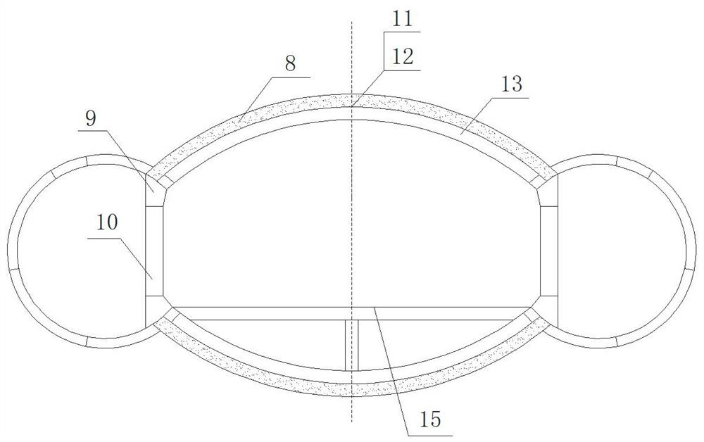
[0072] Such as figure 1 As shown, the subway of the present embodiment, the extension structure of the station comprises a shield tunnel and an intermediate platform connected between two parallel shield tunnels and communicated with the shield tunnel;

[0073] Wherein, the intermediate platform includes a top lining unit and a bottom lining unit, side columns and a structural floor 15, and the top lining unit and the bottom lining unit are arranged between the shield tunnels and are symmetrical up and down, and both the top lining unit and the bottom lining unit include outer The curved steel pipe layer distributed at intervals, the waterproof layer and the station lining 13 arranged in sequence inside the curved steel pipe layer. The diameter of the curved steel pipe in the curved steel pipe layer is 40cm, the radius of curvature is 700~1200m, preferably 900cm, and the length of each section of the curved steel pipe is 0.8~1.0m. Adjacent steel pipes are connected by welding...

Embodiment 2

[0086] The subway of present embodiment, station extension structure are identical with embodiment 1.

[0087] The subway and the station expansion method based on the steel pipe concrete beam insertion method of the present embodiment are specifically realized by the following steps:

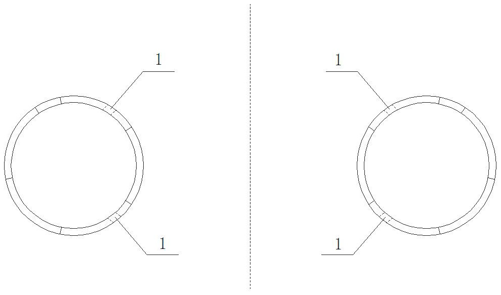
[0088] (1) Upper and lower perforations 1 are respectively set on the opposite positions of the shield segments of the two parallel shield tunnels. The diameter of the perforations is greater than the diameter of the curved steel pipe by ±3mm, so that the curved steel pipe can be jacked smoothly.

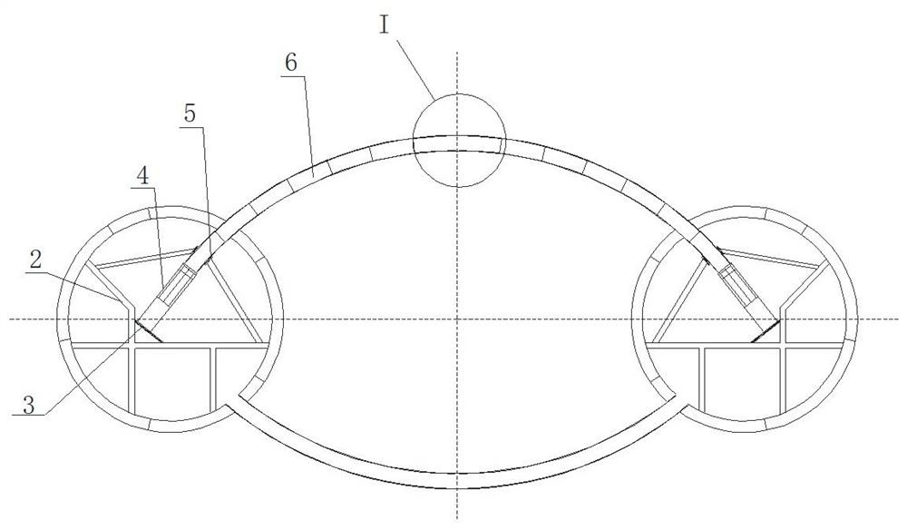
[0089](2) Set up the reaction force frame 2 in the shield tunnel on both sides, fix the reaction force support 3 and the guide frame 5 on the reaction force support 2, set the jacking oil cylinder 4 on the reaction force support 3, so that the jacking The telescopic rod of the oil cylinder 4 coincides with the central axis of the perforation 1 in step (1), and the guiding direction of the guide frame...


PUM


Abstract

The invention relates to a subway station extension method and structure based on a concrete-filled steel tube beam insertion method. The subway station extension method comprises the steps that a transverse through middle platform is built between existing bidirectional parallel shield tunnels to form an extension structure; and corresponding upper through holes and lower through holes are obliquely formed in segments of the two shield tunnels, jacking bent steel pipes are inserted from the through holes to be transversely connected to serve as external supports, a lining structure is constructed after soil is excavated on the inner side, and through connection is achieved after the segments at shield tunnel connectors are detached. Small expansion, downward storey addition and step-by-step expansion can be achieved, and the subway station extension method is suitable for expansion of subway stations with strict control over ground displacement and ground surface settlement and construction of shallow soil, soft stratums and large-span underground spaces.

Description

technical field [0001] The invention relates to the technical field of subway station engineering construction, in particular to a subway station extension method and structure based on a steel pipe concrete beam insertion method. Background technique [0002] The shield tunneling method has become an important construction method in the construction of subways in my country, and has become a preferred method. However, problems such as too short division of shield construction sections, low utilization rate of equipment, and long waiting time for shield machines have restricted the development and application of shield technology in my country. One of the main reasons for these problems is that there is no good Solve the contradiction between the construction of the shield section and the construction of the station in terms of construction speed and organization. [0003] Chinese patent ZL201310468894.2 discloses a construction method for the expansion of the main structure...

Claims


Application Information

Patent Timeline
Patent Type & Authority Applications(China)
IPC IPC(8): E21D9/06E21D11/18E21D11/10E21D11/38E21D11/08
CPCE21D9/06E21D9/0607E21D11/18E21D11/10E21D11/38E21D11/08
Inventor 向亮王飞向阳陈敬军靳宝成尹陇娟刘赪刘建红何冠男
Owner CHINA RAILWAY FIRST SURVEY & DESIGN INST GRP
Why Eureka
Try Eureka