Low-cavitation-allowance low-pressure pulsation centrifugal pump

A NPSH and low pressure technology, applied in the direction of pumps, pump components, non-variable pumps, etc., can solve the problem of the ability of the inducer to reduce NPSH, the large range of pressure and speed changes, and the reduction of NPSH To reduce the amount of excavation, smooth flow, and reduce infrastructure investment

Pending Publication Date: 2018-04-24
SHANDONG SHUANGLUN
View PDF0 Cites 4 Cited by
  • Summary
  • Abstract
  • Description
  • Claims
  • Application Information

AI Technical Summary

Problems solved by technology

Although the swirling flow of the fluid at the inlet can be stabilized by the flow stabilizer, the substantive shortcomings of this structure are: first, the thickness of the blade of the inducer is critical to its ability to reduce the NPSH, and the thicker the blade The thinner the better, especially the thickness of the rim, but the thickness of the common casting process blades is difficult to meet the design requirements, and the ability of the inducer to reduce the NPSH will be greatly reduced; There is a certain width between the two blades. The liquid between the two blades is different from the working surface of the blades, and the work done by the blades is also different. The liquid close to the working surface of the blades gets more energy, and the liquid far away from the working surface of the blades obtains more energy. The liquid near the back gets relatively less energy, so the pressure and velocity of the liquid at the outlet of the impeller from the working surface of the blade to the back of the adjacent blade vary greatly, and the gradient is very steep, resulting in very large pressure fluctuations (see Figure 4 )

Method used


Image

  • Low-cavitation-allowance low-pressure pulsation centrifugal pump
  • Low-cavitation-allowance low-pressure pulsation centrifugal pump
  • Low-cavitation-allowance low-pressure pulsation centrifugal pump

Examples


Embodiment Construction

[0022] The present invention will be described below in conjunction with the accompanying drawings and embodiments.

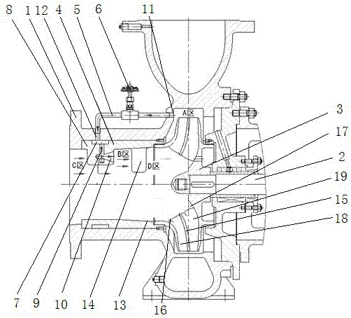
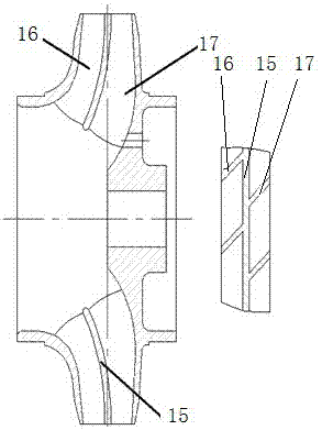
[0023] As shown in the drawings, a low NPSH low pressure pulsation centrifugal pump mainly includes a pump body 1, a pump shaft 2, and an impeller 3. The connection relationship between the pump body 1, pump shaft 2, and impeller 3 is similar to that of the existing The technology is the same, so I won’t go into details here. It is characterized in that an energy conversion device is provided at the entrance of the impeller 3, which includes an energy conversion component 4, a catheter 5 and a regulating valve 6, and the outer wall of the energy conversion component 4 is provided with a fluid guide. Groove 7, the inner wall of the energy conversion component is provided with a jet rib 8 in a circumferential array, and the jet rib 8 is provided with a liquid inlet hole 9 in the radial direction corresponding to the liquid guide groove 7, and a jet hole 10 is arra...


PUM


Abstract

The invention discloses a centrifugal pump with low NPSH and low pressure pulsation, which mainly includes a pump body, a pump shaft and an impeller. There is an energy conversion device, which includes an energy conversion component, a catheter and a regulating valve. The outer wall of the energy conversion component is provided with a fluid guide groove, and the inner wall of the energy conversion component is provided with jet ribs in a circumferential array. The outer wall of the energy conversion component and the pump The suction chamber wall of the body is fixedly connected, the front end of the energy conversion component is fixedly connected with the pump body, the side wall of the high pressure area of ​​the pump body is provided with a liquid outlet through hole, the side wall of the low pressure area is provided with a liquid inlet through hole, and one end of the catheter is It is connected with the liquid outlet through hole, and the other end is connected with the liquid inlet through hole. There is a regulating valve on the catheter tube, and the liquid inlet through hole is connected with the liquid guide groove. It has strong anti-cavitation performance, prolongs the service life, reduces Vibration and noise, stable operation, reliable and other advantages.

Description

technical field [0001] The invention relates to the technical field of hydraulic mechanical engineering, in particular to a low NPSH and low pressure pulsation centrifugal pump. Background technique [0002] In terms of water diversion projects, water pumps are required to have as low a NPSH as possible, which can reduce the excavation of the foundation of the entire pump house and reduce the amount of infrastructure investment. Under the premise of the same pump room height, the use of low NPSH pumps can slow down or even eliminate the phenomenon of blade perforation caused by cavitation, and avoid unplanned downtime maintenance and losses. [0003] At present, the method of reducing the NPSH of the centrifugal pump mainly focuses on increasing the inlet area of ​​the blade, but because the impeller structure size is limited by the flow and head design parameters, the effect of reducing the NPSH of the pump by this method is very good. limited. [0004] In order to solve ...

Claims


Application Information

Patent Timeline
Patent Type & Authority Applications(China)
IPC IPC(8): F04D29/22F04D29/24F04D29/66
CPCF04D29/2222F04D29/24F04D29/669
Inventor 于泳水王家斌姜绍东刘军
Owner SHANDONG SHUANGLUN
Why Eureka
Try Eureka