Construction method of support-free prefabricated assembly type shield tunnel air shaft structure

A technology of shield tunneling and construction method, which is applied in mine/tunnel ventilation, tunnel, tunnel lining and other directions, and can solve the problems of non-protrusion, limited mileage, long construction period, etc.

Inactive Publication Date: 2021-04-30
绍兴市柯桥区轨道交通集团有限公司
View PDF7 Cites 4 Cited by
  • Summary
  • Abstract
  • Description
  • Claims
  • Application Information

AI Technical Summary

Problems solved by technology

The construction of deep foundation pits requires a large number of temporary support structures, the construction period is long, and it will also cause a lot of waste of building materials. At the same time, the increase in the depth of the foundation pit greatly increases the construction risk.
In the past, due to the limited mileage of a single excavation of the shield tunnel, the deep foundation pit of the wind shaft can be used as the intermediate working shaft of the shield tunnel, and the construction period and waste of materials are not prominent.
However, at present, the mileage of a single excavation of a shield tunnel is far greater than the limitation of the distance between the air shafts. Therefore, it is urgent to invent a shield tunnel air shaft structure that does not need to be provided with a support structure and is constructed in a prefabricated and assembled manner. Rapid, safe and low-impact construction of air shafts for structural tunnels

Method used


Image

  • Construction method of support-free prefabricated assembly type shield tunnel air shaft structure

Examples


Embodiment Construction

[0028] The present invention will be further elaborated and illustrated below in conjunction with the accompanying drawings and specific embodiments. The technical features of the various implementations in the present invention can be combined accordingly on the premise that there is no conflict with each other.

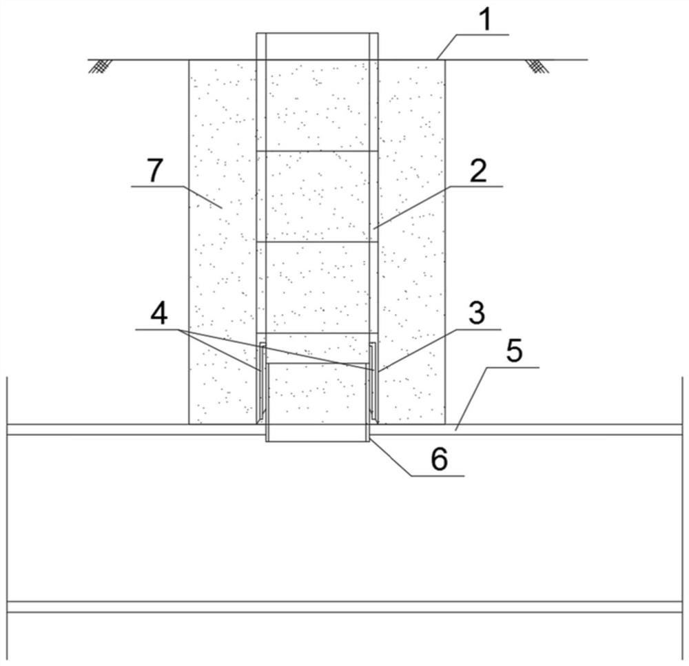
[0029] In a preferred embodiment of the present invention, a construction method for the air shaft structure of an unsupported prefabricated and assembled shield tunnel is provided, the purpose of which is to avoid pouring concrete at the construction site and instead adopt the form of prefabricated and assembled shield tunneling Construction of the air shaft structure of the tunnel.

[0030] Such as figure 1 As shown, the air shaft structure is assembled by multiple sections of prefabricated pipe joints. The prefabricated pipe joints can be designed and determined according to the cross-sectional size of the air shaft and the depth of the air shaft. It is process...


PUM


Abstract

The invention discloses a construction method of a support-free prefabricated assembly type shield tunnel air shaft structure. The method includes the steps that after shield tunneling is completed, high-pressure jet grouting piles are adopted to conduct reinforcement and water stop on soil in an air shaft construction range at a designed air shaft position, then the prefabricated air shaft structure is hoisted in place in sections, excavation is conducted in the air shaft structure, the air shaft structure gradually sinks by means of self weight, and excavation is performed until the excavation is performed above a constructed shield tunnel structure; and after reliable reinforcing and water stopping are conducted at a connecting position of a shield and the air shaft structure, holes are formed in the top of the shield tunnel structure in the air shaft structure, steel pipe pieces are adopted as pipe pieces for hole forming, then the steel pipe pieces of a shield tunnel are connected with the air shaft structure in a welded mode through steel sleeves, and the construction of the air shaft structure is completed. According to the construction method of the support-free prefabricated assembly type shield tunnel air shaft structure, an air shaft deep foundation pit supporting structure can be constructed, so that the safe, rapid, economical and environment-friendly construction purpose of a tunnel air shaft is achieved, and the method is suitable for construction of urban shield tunnel engineering.

Description

technical field [0001] The invention belongs to the field of urban shield tunnel engineering, and in particular relates to a construction method for an air shaft structure of an unsupported prefabricated assembled shield tunnel. Background technique [0002] With the rapid development of urban construction in my country, the intensity of underground space development in major cities continues to increase, and the application of shield tunnels is becoming more and more common. At the same time, the diameter of shield tunnels continues to increase, and the buried depth of tunnels is also getting deeper. , because the underground tunnel is a relatively closed space, when used as a subway or urban road, the ventilation and smoke exhaust requirements of the tunnel are very high, and the air shaft structure on the ground needs to be set at a certain distance. The air shaft is generally set in the middle of the tunnel section, and these positions are generally the deepest buried pos...

Claims


Application Information

Patent Timeline
Patent Type & Authority Applications(China)
IPC IPC(8): E21D5/11E21F1/00E21D11/38
CPCE21D5/11E21F1/006E21D11/386
Inventor 何峰徐永祥鲁麓树陈叶丰傅承诚陈云飞郦大根金美芳魏征傅了一
Owner 绍兴市柯桥区轨道交通集团有限公司
Why Eureka
Try Eureka