Drive arrangement for electric vehicle and method for power shifting

A driving mechanism, a technology for electric vehicles, applied in the direction of electric power units, power units, vehicle components, etc., can solve problems such as the inability to realize power shifting

Pending Publication Date: 2021-04-30
ZF FIEDRICHSHAFEN AG
View PDF0 Cites 0 Cited by
  • Summary
  • Abstract
  • Description
  • Claims
  • Application Information

AI Technical Summary

Problems solved by technology

Power shifting is not possible with this transaxle with only one electric drive machine and only one shift transmission and axle differential

Method used


Image

  • Drive arrangement for electric vehicle and method for power shifting
  • Drive arrangement for electric vehicle and method for power shifting

Examples


Embodiment Construction

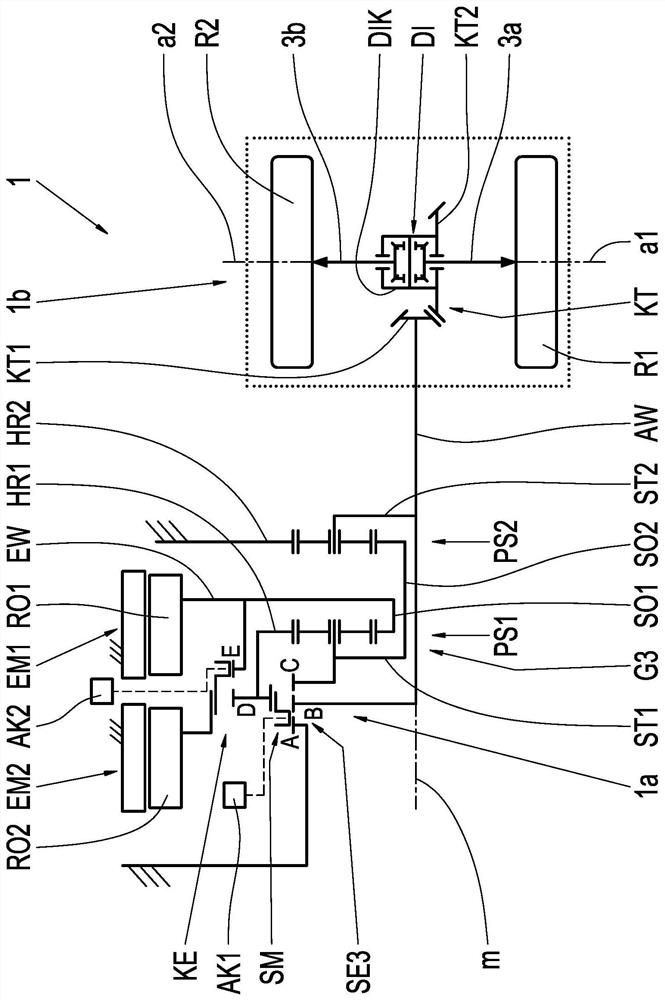
[0023] figure 1 As a first exemplary embodiment of the invention, a first drive mechanism 1 of an electrically driveable vehicle (hereinafter referred to simply as an electric vehicle) is shown as a so-called central drive. The drive mechanism 1 comprises, on the one hand, a drive unit 1a consisting of a first electric machine EM1 with a first rotor RO1, a second electric machine EM2 with a second rotor RO2, a third gear with a shifting device SE3 and a coupling device KE. The shift transmission G3 constitutes. The electric machines EM1 , EM2 have a common axis of rotation m which extends in the longitudinal direction of the electric vehicle. The axis of rotation m is at the same time the axis of symmetry of the shift transmission G3, only the upper half of which is shown. The drive train 1 also includes a conventional axle 1b with a first drive wheel R1 and a second drive wheel R2 with associated wheel axes a1, a2, an axle differential DI, and two differentials Output shaf...


PUM


Abstract

The invention relates to a drive arrangement for an electric vehicle and a method for power shifting. The drive arrangement comprises: first and second drive wheels (R1, R2) with wheel axles (a1, a2), a first electric machine (EM1) and a second electric machine (EM2) with a common rotational axis (m), a manual transmission (G3) with a transmission input shaft (EW) and a transmission output shaft (AW), and an axle differential (DI) with a differential input (DIK) and two differential output shafts (3a, 3b), the first electric machine (EM1) being connected to the transmission input shaft (EW), and the transmission output shaft (AW) being connected to the differential input (DIK), and the second electric machine (EM2) can, if necessary, be engaged as an additional drive.

Description

technical field [0001] The present invention relates to a drive mechanism for an electric vehicle comprising: a first drive wheel and a second drive wheel having a wheel axis, a first electric machine and a second electric machine having a common axis of rotation, a transmission input shaft and transmission output shaft shift transmission, and axle differential. The invention also relates to a method for performing a gearshift under power by means of a shifting device and a coupling device of a shift transmission (power shifting method). Background technique [0002] In the earlier application with docket number 10 2019 202 994.9 a drive unit for an electric vehicle is disclosed, which has an electric machine and a three-speed shift transmission or a two-speed shift transmission, in which a shift A device having three or two shifting elements for shifting three or two gears. By omitting shifting elements, a three-speed transmission can be used as a two-speed transmission. ...

Claims


Application Information

Patent Timeline
Patent Type & Authority Applications(China)
IPC IPC(8): F16H3/66F16H61/04F16H61/02
CPCF16H3/66F16H61/04F16H61/0204F16H2200/0039F16H2200/201B60K1/02B60Y2400/73F16H2200/0021F16H2200/0034F16H2200/2007F16H2200/2094F16H2200/2043F16H2200/2097F16H2200/2041F16H3/727
Inventor J·格吕克勒K·波恩特拉格S·雷纳S·斯普勒M·特鲁本巴赫J·卡尔滕巴赫
Owner ZF FIEDRICHSHAFEN AG
Why Eureka
Try Eureka