Method for measuring uniformity of icing grid and cloud and mist field
What is AI technical title?
AI technical title is built by PatSnap AI team. It summarizes the technical point description of the patent document.
A measurement method and uniformity technology, applied in the field of icing grid and cloud field uniformity measurement, can solve the problems of low measurement efficiency and poor measurement accuracy, and achieve high measurement efficiency, high measurement accuracy, and high measurement accuracy. The effect of measuring efficiency
Active Publication Date: 2021-04-30
LOW SPEED AERODYNAMIC INST OF CHINESE AERODYNAMIC RES & DEV CENT
View PDF18 Cites 2 Cited by
Summary
Abstract
Description
Claims
Application Information
AI Technical Summary
This helps you quickly interpret patents by identifying the three key elements:
Problems solved by technology
Method used
Benefits of technology
Problems solved by technology
[0010] The purpose of the present invention is to provide a method for measuring the uniformity of the icing grid and the cloud field, aiming to solve the technical problems of low measurement efficiency and poor measurement accuracy of the uniformity of the cloud field in the prior art
Method used
Image
Click on the blue label to locate the original text in one second.
Reading with bidirectional positioning of images and text.
Examples
Embodiment 1
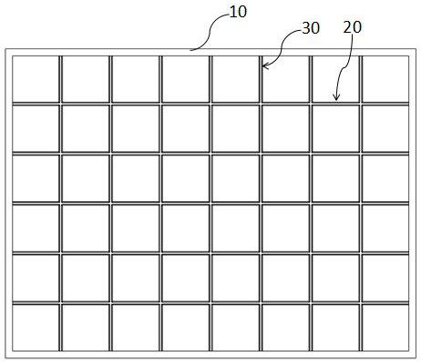
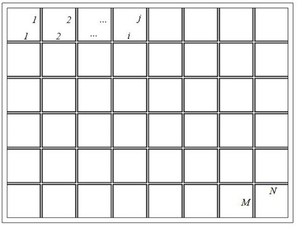
[0043] like figure 1The above is a schematic diagram of an icing grid in Embodiment 1 of the present invention, which includes a frame body 10, vertical grid bars 20 and horizontal grid bars 30, and the vertical grid bars 20 and the horizontal grid bars 30 Distributed in the frame body 10 in a criss-cross manner, the vertical grid bars 20 divide the horizontal grid bars 30 into N horizontal units, and the serial numbers of the horizontal units are marked as i , 1≤i≤N , the horizontal grid bar 30 divides the vertical grid bar 20 into M vertical units, and the serial numbers of the vertical units are denoted as j , 1≤j≤M ;
[0044] like figure 2 Shown is a schematic diagram of the horizontal unit and the vertical unit in Embodiment 1 of the present invention, the horizontal unit is a small section on the horizontal grid bar 30 , and the vertical unit is a small section on the vertical grid bar 20 .
[0045] The criss-cross distribution in Embodiment 1 of the present inv...
Embodiment 2
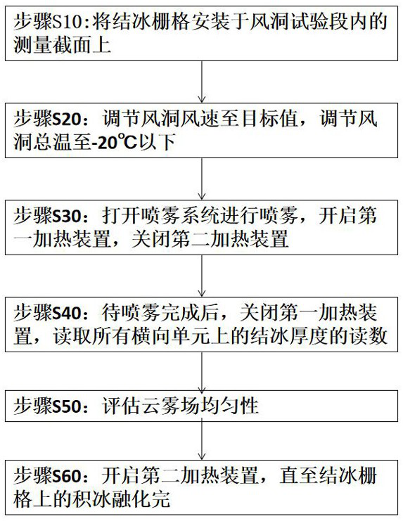
[0054] like Figure 4 Shown is a schematic diagram of a method for measuring the uniformity of the cloud field in Embodiment 2 of the present invention, and the method for measuring the uniformity of the cloud field includes the following steps:
[0055] Step S10: the above-mentioned icing grid is installed on the measurement section in the wind tunnel test section;
[0056] Step S20: Adjust the wind speed of the wind tunnel to the target value, and adjust the total temperature of the wind tunnel to below -20°C;
[0057] Step S30: Turn on the spray system for spraying, turn on the first heating device 23, and turn off the second heating device 24; therefore, no ice will form on the outer surface 211 of the bump 21, and thus will not affect the collection of water droplets. Therefore, Has higher measurement accuracy;
[0058] Step S40: After the spraying is completed, turn off the first heating device 23, read the readings of the thickness of ice on all horizontal units, and ...
PUM
Abstract
The invention is suitable for the technical field of wind tunnel measurement, and provides a method for measuring the uniformity of an icing grid and cloud and mist field. The icing grid comprises a frame body, vertical grid bars and transverse grid bars; the vertical grid bars and the transverse grid bars are distributed in the frame body in a criss-cross manner, and the vertical grid bars and the transverse grid bars are arranged in the frame body in a staggered manner. The transverse grid bars are divided into N transverse units by the vertical grid bars, and the vertical grid bars are divided into M vertical units by the transverse grid bars; protruding blocks extending in the axial direction are symmetrically arranged on the front edges of the vertical grid bars and the front edges of the transverse grid bars, grooves are formed between the protruding blocks, first heating devices are arranged outside the outer side faces of the protruding blocks, and second heating devices are arranged on the inner side faces of the protruding blocks and inside the bottom faces of the grooves; and scale marks are arranged outside the inner side faces of the protruding blocks. According to the invention, the measurement efficiency and the measurement precision of the cloud and mist field uniformity can be improved simultaneously.
Description
technical field [0001] The invention belongs to the technical field of wind tunnel measurement, in particular to a method for measuring the uniformity of an icing grid and a cloud field. Background technique [0002] The uniformity of the cloud and fog field refers to the uniformity of the spatial distribution of the liquid water content of the icing cloud and fog in the wind tunnel test section, and is one of the important indicators for evaluating the quality of the cloud and fog field in the icing wind tunnel. [0003] The most commonly used test method for the uniformity of cloud and fog field is carried out by means of icing grid, which refers to a grid-shaped module connected together by several flat rectangular parallelepiped grid bars in the horizontal and vertical directions. The spatial distribution of the frosted ice thickness on the front surface of the icing grid can indirectly reflect the spatial distribution of the liquid water content, so that the uniformity ...
Claims
Application Information
Patent Timeline
Application Date:The date an application was filed.
Publication Date:The date a patent or application was officially published.
First Publication Date:The earliest publication date of a patent with the same application number.
Issue Date:Publication date of the patent grant document.
PCT Entry Date:The Entry date of PCT National Phase.
Estimated Expiry Date:The statutory expiry date of a patent right according to the Patent Law, and it is the longest term of protection that the patent right can achieve without the termination of the patent right due to other reasons(Term extension factor has been taken into account ).
Invalid Date:Actual expiry date is based on effective date or publication date of legal transaction data of invalid patent.
Patent Type & AuthorityApplications(China)
IPC IPC(8): G01M9/06
CPCG01M9/06
Inventor郭奇灵郭向东王梓旭易贤刘森云杨升科
OwnerLOW SPEED AERODYNAMIC INST OF CHINESE AERODYNAMIC RES & DEV CENT

