Insulating pull rod for high-voltage switchgear

A technology of insulating tie rods and high-voltage switches, which is applied to insulators, electrical switches, insulators, etc., can solve the problems of safety risks in the discharge of insulating tie rods

Pending Publication Date: 2021-04-30
CHINA ELECTRIC POWER RES INST +3
View PDF0 Cites 0 Cited by
  • Summary
  • Abstract
  • Description
  • Claims
  • Application Information

AI Technical Summary

Problems solved by technology

[0004] In view of this, the present invention proposes an insulating pull rod for high-voltage switchgear, aiming at solving the problem of safety risk caused by discharge between the live part and the insulating part on the existing insulating pull rod

Method used


Image

  • Insulating pull rod for high-voltage switchgear
  • Insulating pull rod for high-voltage switchgear

Examples


Embodiment Construction

[0020] Exemplary embodiments of the present disclosure will be described in more detail below with reference to the accompanying drawings. Although exemplary embodiments of the present disclosure are shown in the drawings, it should be understood that the present disclosure may be embodied in various forms and should not be limited by the embodiments set forth herein. Rather, these embodiments are provided for more thorough understanding of the present disclosure and to fully convey the scope of the present disclosure to those skilled in the art. It should be noted that, in the case of no conflict, the embodiments of the present invention and the features in the embodiments can be combined with each other. The present invention will be described in detail below with reference to the accompanying drawings and examples.

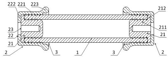
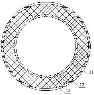
[0021] see figure 1 , which is a front view of an insulating tie rod for a high-voltage switchgear provided by an embodiment of the present invention. As sh...


PUM


Abstract

The invention provides an insulating pull rod for high-voltage switchgear. The insulating pull rod comprises an insulating tube body and two metal joints; the two ends of the insulating tube body are respectively inserted into the two metal joints, and an annular shielding gap is formed between each metal joint and the insulating tube body at the periphery of the insulating tube body and is used for shielding discharge between the insulating tube body and the metal joints. According to the insulating pull rod, the annular shielding gaps are formed between the metal joints and the insulating tube body and at the periphery of the insulating tube body, so that the discharge between the insulating tube body and the metal joints is shielded, and the partial discharge of the insulating pull rod, especially the joint of the metal joint and the insulating tube body, is avoided; therefore, the electric field uniformity of the insulating pull rod is ensured, the insulating property of the insulating pull rod is further ensured, and the insulating pull rod can work safely and reliably.

Description

technical field [0001] The invention relates to the technical field of composite insulating materials and high-voltage switches, in particular to an insulating tie rod for high-voltage switchgear. Background technique [0002] The insulating rod is a key part of the high-voltage switchgear, which is used to transmit the movement from the grounding part to the insulating member of the high potential part to realize the on-off of the electrical connection. The structure of the insulating rod is thin and long, and it bears certain tensile and compressive loads and instantaneous operating impulse voltage during the opening and closing operation of the circuit breaker, so it is required to have excellent mechanical and electrical properties. [0003] However, at present, discharges are likely to occur between the live part and the insulating part on the insulating pull rod, which affects the electrical performance of the insulating pull rod and causes a safety risk when the insul...

Claims


Application Information

Patent Timeline
Patent Type & Authority Applications(China)
IPC IPC(8): H01H3/02H01H9/48H01B17/58H01B17/60
CPCH01B17/583H01B17/60H01H3/02H01H9/48
Inventor 陈允韩先才刘志刚崔博源肖刚殷禹张鹏飞王浩然吴昱怡刘焱
Owner CHINA ELECTRIC POWER RES INST
Why Eureka
Try Eureka