Vacuum arc-extinguishing chamber with composite contact structure

A vacuum interrupter and composite contact technology, applied in high-voltage air circuit breakers, electrical components, electrical switches, etc., to achieve the effect of reducing over-travel, reducing distance, and reducing requirements

Active Publication Date: 2021-04-30
PINGGAO GRP +2
View PDF12 Cites 1 Cited by
  • Summary
  • Abstract
  • Description
  • Claims
  • Application Information

AI Technical Summary

Problems solved by technology

[0005] The purpose of the present invention is to provide a vacuum interrupter with a compound contact structure to solve the requirement in the prior art that the static contacts only rel

Method used


Image

  • Vacuum arc-extinguishing chamber with composite contact structure
  • Vacuum arc-extinguishing chamber with composite contact structure
  • Vacuum arc-extinguishing chamber with composite contact structure

Examples


specific Embodiment 1

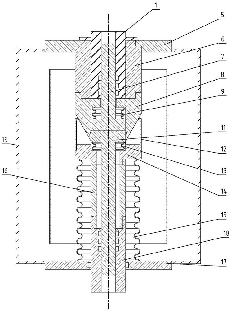
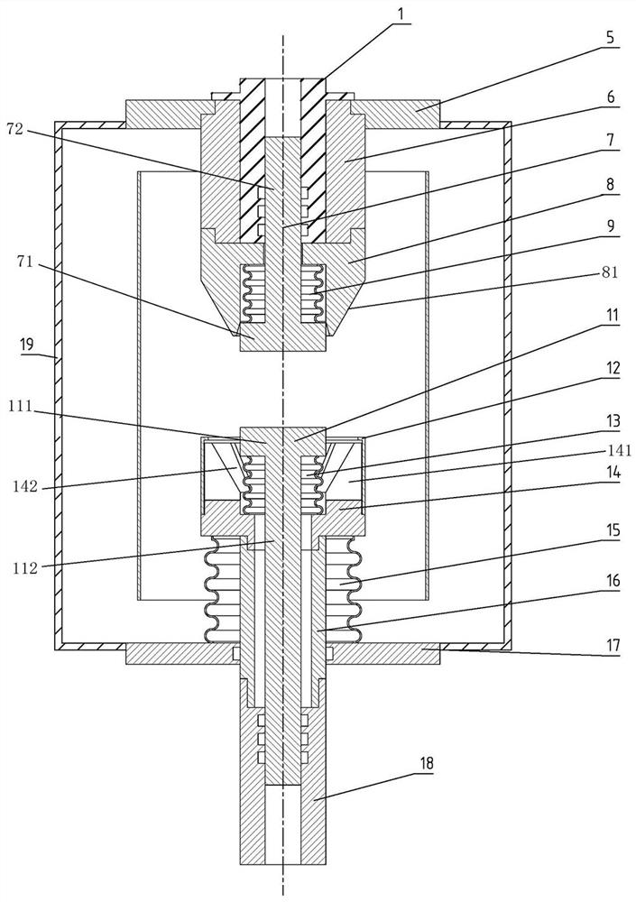
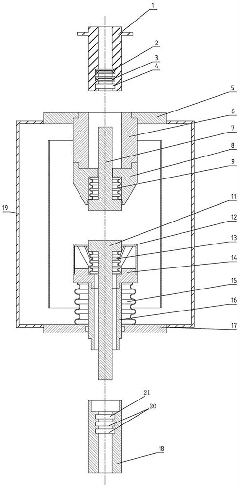
[0046] In the vacuum interrupter with compound contact structure provided by this embodiment, both the static arc contact 7 and the dynamic arc contact 11 can move relative to the corresponding main contacts, which can reduce the number of single static arc contacts 7 The moving distance can relatively reduce the space occupied by the static end of the entire vacuum interrupter, and optimize the overall performance of the vacuum interrupter.

[0047] The specific structure of the vacuum interrupter is as follows: Figure 1 to Figure 3 As shown, the vacuum interrupter in this embodiment includes an interrupter housing 19, and a static contact structure and a moving contact structure are arranged inside the arc extinguishing chamber housing 19, and the static contact structure is located above the moving contact structure. The arc extinguishing chamber housing 19 here includes a middle circumferential housing, an upper cover 5 at the upper end and a lower cover 17 at the lower e...

specific Embodiment 2

[0071] The main difference between it and Embodiment 1 is: in Embodiment 1, in the embodiment, the static main contact has a tapered outer peripheral surface, and the moving main contact has a tapered concave portion. In this embodiment, the moving main contact has a tapered outer peripheral surface, and the static main contact has a tapered concave portion, which can also realize the tapered mating of the two main contacts and effectively increase the contact area.

[0072] Generally speaking, the moving contact structure is arranged at the bottom, and the static contact structure is arranged at the top. In fact, in other embodiments, the moving contact structure can also be arranged at the top, and the static contact structure is arranged at the top. Arranged below.

specific Embodiment 3

[0074] It differs from Embodiment 1 mainly in that: in Embodiment 1, the tapered outer peripheral surface of the static main contact and the tapered inner peripheral surface of the moving main contact are both conical surfaces. In this embodiment, the tapered outer peripheral surface of the static main contact and the tapered inner peripheral surface of the moving main contact can also be pyramidal surfaces, but for the purpose of improving the electric field performance, the edges of the static main contact can be designed rounded structure.


PUM


Abstract

The invention relates to a vacuum arc-extinguishing chamber with a composite contact structure. The vacuum arc-extinguishing chamber comprises: a static contact structure which comprises a static main contact, a static arc contact and a static end corrugated pipe, wherein the static arc contact is movably assembled in the static main contact, and the static end corrugated pipe applies an elastic reset acting force to the static arc contact; and a moving contact structure which comprises a moving main contact, a moving arc contact and a moving end corrugated pipe. The moving arc contact is movably assembled in the moving main contact; and the moving end corrugated pipe applies an elastic reset acting force to the moving arc contact to force the moving arc contact to move towards the static arc contact. The static end corrugated pipe and the moving end corrugated pipe are utilized to enable the static arc contact and the moving arc contact to move relative to the corresponding main contacts, and the protruding amount of the two arc contacts relative to the main contacts is offset by the two arc contacts, so compared with a scheme for offsetting only depending on the movement of the static arc contact, the scheme using the two arc contacts to act can effectively reduce the moving distance of the static arc contact, reduce the overtravel condition of the vacuum arc-extinguishing chamber and lower the requirement for the installation place of the vacuum arc-extinguishing chamber.

Description

technical field [0001] The invention belongs to the technical field of vacuum switches, and in particular relates to a vacuum interrupter with a composite contact structure. Background technique [0002] With the development of the economy, vacuum circuit breakers have gradually replaced sulfur hexafluoride circuit breakers due to their environmental friendliness, long life, and maintenance-free characteristics, and have become a research hotspot at home and abroad. For the vacuum interrupter, the difficulty lies in how to conduct the rated current under normal conditions and break the fault current under fault conditions. [0003] A vacuum interrupter is disclosed in the Chinese utility model patent with the authorized announcement number CN2023076740U. Although the static contacts include separately arranged arc contacts and main contacts, the moving contacts are still the main contacts and arc contacts. One-piece structure, even if the longitudinal magnetic field contact...

Claims


Application Information

Patent Timeline
IPC IPC(8): H01H33/664H01H33/662
CPCH01H33/664H01H33/662H01H33/66261
Inventor 李旭旭毕迎华谭盛武孙广雷何创伟林麟陆静马朝阳李永林刘庆王向克杨帆徐伏刚王晶杨光薛从军齐大翠赵芳帅李小钊刘英英王福亚刘文魁王铭飞刘先保庞素敏李潇张航李新卫关欣
Owner PINGGAO GRP
Why Eureka
Try Eureka