
Wind pressure switch

A technology of air pressure switch and mounting base, which is applied in the direction of electric switches, electrical components, circuits, etc. It can solve the problems of heavy assembly workload, lack of constant temperature function of the installation structure, and affecting the use effect of products.

Active Publication Date: 2021-04-30
红禾朗(兴宁)电工有限公司
View PDF12 Cites 0 Cited by
  • Summary
  • Abstract
  • Description
  • Claims
  • Application Information

AI Technical Summary

Problems solved by technology

Although the existing installation structure can realize the installation of the air pressure switch, there are also the following problems: the assembly workload is large, and screwing operations need to be performed many times, the air pressure switch is inconvenient to disassemble, and the disassembly life is short. Tapping holes are easy to damage, resulting in unstable connection and reduced life of disassembly and assembly; affecting the life of the air pressure switch
In addition, because the air pressure switch is usually used in an environment where the temperature alternates, the inside of the air pressure switch is a closed space. If air is added to the product, water will be generated inside the product due to the temperature difference. If the air pressure switch The presence of water inside will affect the use effect of the product, and the existing installation structure lacks the function of constant temperature

Method used


Image

  • Wind pressure switch
  • Wind pressure switch
  • Wind pressure switch

Examples


Embodiment Construction

[0036] The following will clearly and completely describe the technical solutions in the embodiments of the present invention with reference to the accompanying drawings in the embodiments of the present invention. Obviously, the described embodiments are only some, not all, embodiments of the present invention.

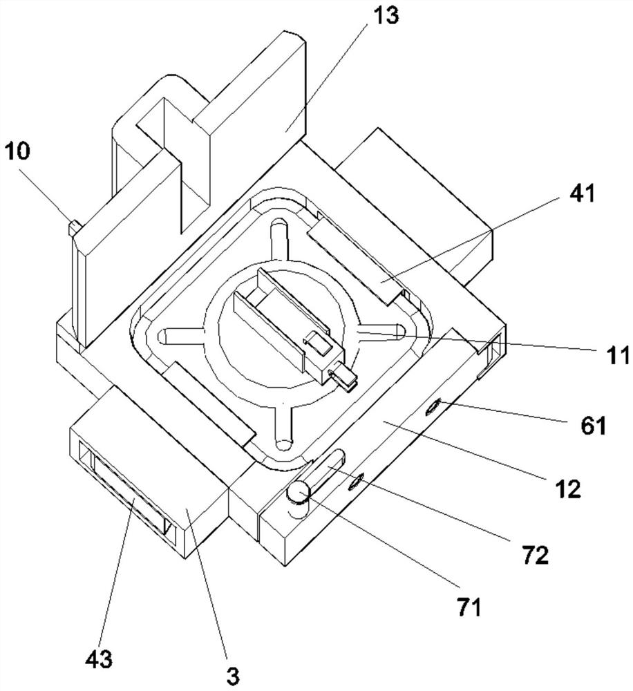
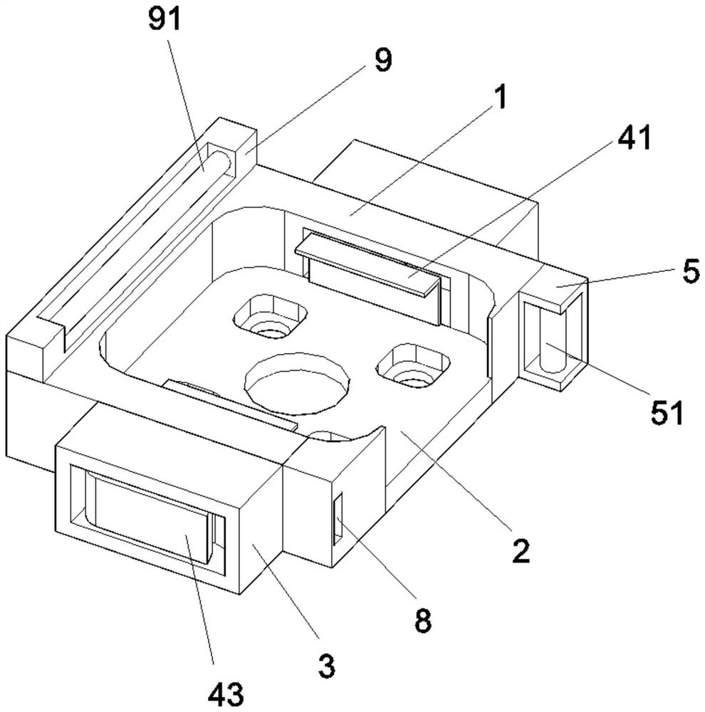
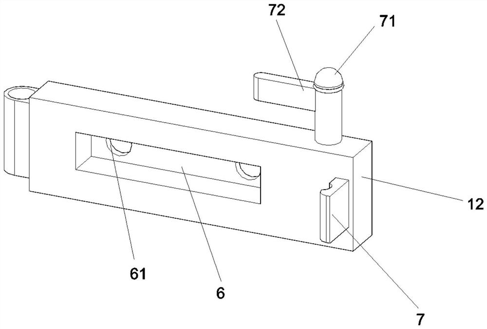
[0037] refer to Figure 1-6 , a wind pressure switch, comprising a mounting base 1, a wind pressure switch body 11, a base side cover 12, a thermal insulation cover 13, the wind pressure switch body 11 is movably installed on the upper surface of the mounting base 1, and the thermal insulation cover 13 is connected to the mounting base 1 One end of the surface is rotatably connected, and the base side cover 12 is rotatably connected to one end of the side surface of the installation base 1. The installation base 1, the base side cover 12 and the heat preservation cover 13 are all made of glass fiber board with low thermal conductivity;

[0038] By setting the heat pr...


PUM


Abstract

The invention belongs to the technical field of wind pressure switches, and particularly relates to a wind pressure switch which comprises a mounting base, a wind pressure switch body, a base side cover and a heat preservation cover. The wind pressure switch body is movably mounted on the upper surface of the mounting base, and the heat preservation cover is rotatably connected with one end of the upper surface of the mounting base. According to the wind pressure switch, through the arrangement of a quick release device, when the wind pressure switch body needs to be installed and only a quick release handle needs to be pulled up, a quick release clamping hand can be pulled by the quick release handle to be folded, at the moment, the wind pressure switch body is placed into an installation base, and when the quick release handle is closed, the quick release clamping hand can extend out under the action of a first spring, and the wind pressure switch is clamped; when the wind pressure switch body needs to be dismounted, the wind pressure switch body can be pulled out only by pulling up the quick dismounting handle, so that the quick mounting and dismounting of the wind pressure switch body are achieved, and the problem that an existing wind pressure switch is inconvenient to mount and dismount is effectively solved.

Description

technical field [0001] The invention relates to the technical field of air pressure switches, in particular to an air pressure switch. Background technique [0002] The wind pressure switch is a detection element, which is installed on the equipment that controls the wind pressure, and the micro switch is pushed by the static pressure of the gas, so as to realize the control equipment circuit or pipeline on-off. The wind pressure switch is mainly installed on the equipment. Although the existing installation structure can realize the installation of the air pressure switch, there are also the following problems: the assembly workload is large, and screwing operations need to be performed many times, the air pressure switch is inconvenient to disassemble, and the disassembly life is short. Tapping holes are easy to damage, resulting in unstable connection and reduced disassembly life; affecting the life of the air pressure switch. In addition, because the air pressure switc...

Claims


Application Information

Patent Timeline
IPC IPC(8): H01H35/26
CPCH01H35/26Y02E10/72
Inventor 段文博
Owner 红禾朗(兴宁)电工有限公司
Learn More