Motor rotor and motor

A motor rotor and rotor technology, applied in the direction of electrical components, electromechanical devices, electric components, etc., can solve the problem of high cost of wind power generators, achieve sufficient demagnetization resistance, cost reduction, and high air gap magnetic flux density.

Active Publication Date: 2021-04-30
XINJIANG GOLDWIND SCI & TECH
View PDF6 Cites 0 Cited by
  • Summary
  • Abstract
  • Description
  • Claims
  • Application Information

AI Technical Summary

Problems solved by technology

[0005] Therefore, the object of the present invention is to provide a motor rotor with a novel structure to solve the problem of high cost of wind power generators caused by existing electronic rotors

Method used


Image

  • Motor rotor and motor
  • Motor rotor and motor
  • Motor rotor and motor

Examples


Embodiment Construction

[0026] Embodiments according to the present invention will now be described in detail with reference to the accompanying drawings, examples of which are shown, in which like reference numerals refer to like components throughout. In the following embodiments, a motor with an inner stator and an outer rotor is used as an example to describe the motor rotor and the motor of the present invention, and this description is also applicable to a motor with an outer stator and an inner rotor.

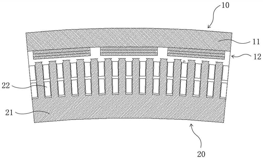
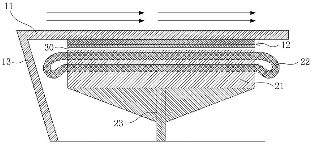
[0027] Such as figure 1 and figure 2 As shown, the motor includes a motor rotor 10 and a motor stator 20. An air gap 30 is formed between the motor rotor 10 and the motor stator 20. The motor can be in the form of an outer rotor with an inner stator, or with an inner rotor with an outer stator. In this application, the outer rotor motor is taken as an example to illustrate the specific implementation of the solution of the application, but it is not limited to the outer rotor motor. Through c...


PUM


Abstract

The invention provides a motor rotor and a motor. The motor rotor comprises a rotor magnet yoke and a magnetic pole installed on the rotor magnet yoke, the magnetic pole comprises a plurality of magnetic steel units, each magnetic steel unit comprises at least two pieces of magnetic steel stacked in the radial direction of the rotor magnet yoke, and the magnetic energy product of the magnetic steel closest to the rotor magnet yoke in the at least two pieces of magnetic steel is greater than the magnetic energy product of the magnetic steel farthest from the rotor magnet yoke. According to the motor rotor provided by the invention, each magnetic steel unit comprises at least two pieces of magnetic steel stacked in the radial direction of the rotor magnet yoke, and the magnetic energy product of the magnetic steel closest to the rotor magnet yoke is greater than the magnetic energy product of the magnetic steel farthest from the rotor magnet yoke, so that on the premise that the demagnetization of the motor rotor can be avoided, the rare earth consumption of the magnetic steel and the motor cost are reduced.

Description

technical field [0001] The invention relates to the technical field of motors, in particular to a motor rotor and a motor capable of reducing the amount of rare earth used. Background technique [0002] The permanent magnet generator has become the main technical model in the field of wind power generators due to its characteristics of high torque density, high power generation efficiency and no need for additional excitation equipment. The rotor permanent magnets that provide air gap flux in permanent magnet generators usually use NdFeB permanent magnets. [0003] NdFeB permanent magnets can be divided into M material, H material, SH material, UH material, EH material, AH material, etc. according to the order of intrinsic coercive force from low to high. The physical quantity of demagnetization ability and the intrinsic coercive force are closely related to the temperature stability of NdFeB permanent magnets. The higher the intrinsic coercive force, the better the tempera...

Claims


Application Information

Patent Timeline
Patent Type & Authority Applications(China)
IPC IPC(8): H02K1/27
CPCH02K1/272H02K1/2786Y02E10/72
Inventor 高亚州夏静陈艳双
Owner XINJIANG GOLDWIND SCI & TECH
Why Eureka
Try Eureka