Rotor of self-starting permanent magnet synchronous motor

A permanent magnet synchronous and motor technology, which is applied to synchronous machine parts, electric components, magnetic circuits, etc., can solve the problems of low utilization rate of permanent magnet materials, excessive quantity and wide width, and weakened mechanical strength of punching sheets. Achieve the effect of improving ventilation effect, low manufacturing cost and simple processing

Pending Publication Date: 2020-02-21
XIANGTAN ELECTRIC MFG CORP LTD
View PDF0 Cites 0 Cited by
  • Summary
  • Abstract
  • Description
  • Claims
  • Application Information

AI Technical Summary

Problems solved by technology

[0004] The existing technology is used in a rotor punching sheet of a self-starting permanent magnet synchronous motor. The magnetic steel groove adopts a "W" shape, and a rib is added in the middle of a "W" shaped magnetic steel groove to increase the mechanical strength of the punching sheet. , but the number of such ribs should not be too many or too wide, which will easily cause serious magnetic steel leakage, and the existing punching pieces can only be used in permanent magnet synchronous motors with a small number of poles
For permanent magnet synchronous motors with multiple poles, the punching sheet with this structure needs multiple "W"-shaped magnetic steel grooves. The large number of magnetic steel grooves and ribs makes the mechanical strength of the punching sheet weaker, and the utilization rate of permanent magnet materials Too low to meet the design requirements

Method used


Image

  • Rotor of self-starting permanent magnet synchronous motor
  • Rotor of self-starting permanent magnet synchronous motor
  • Rotor of self-starting permanent magnet synchronous motor

Examples


Embodiment Construction

[0022] In order to enable those skilled in the art to better understand the technical solution of the present invention, the present invention will be described in detail below in conjunction with the accompanying drawings. The description in this part is only exemplary and explanatory, and should not have any limiting effect on the protection scope of the present invention. .

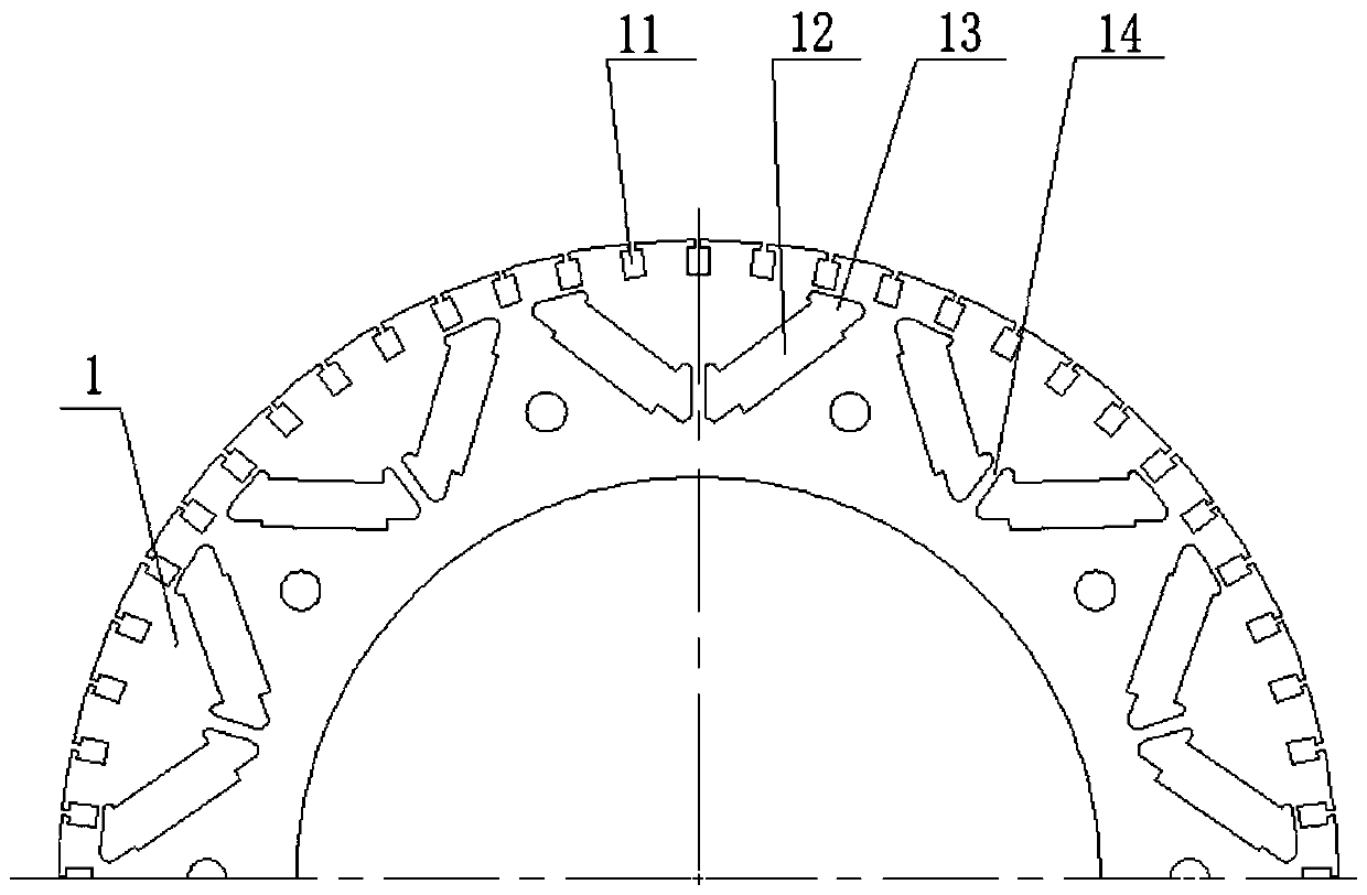
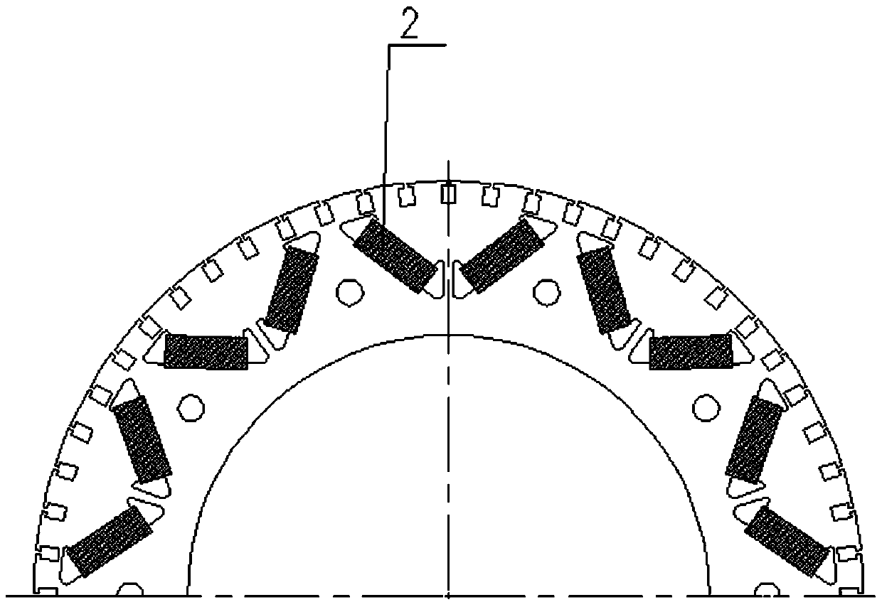
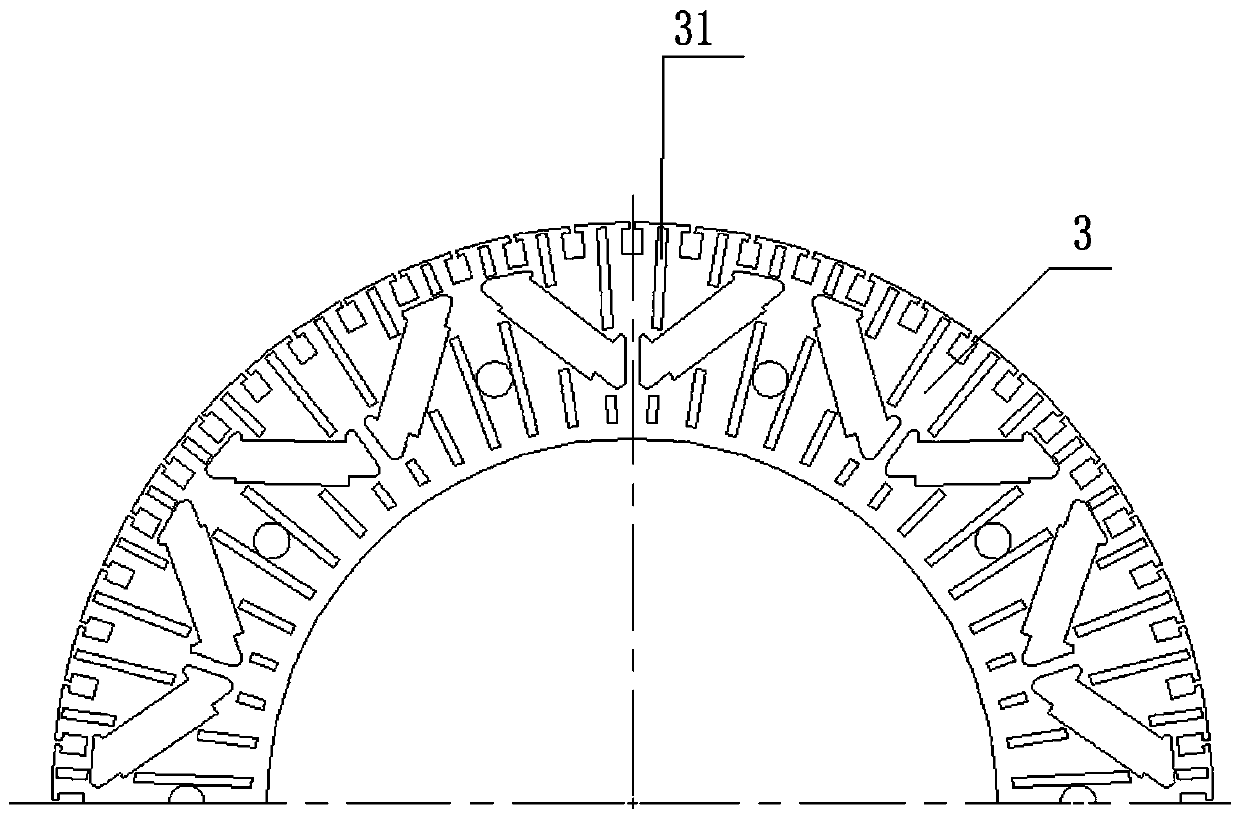
[0023] like Figure 1-Figure 5 As shown, the present invention provides a self-starting permanent magnet synchronous motor rotor structure, which is specifically applied to a multi-pole high-voltage high-efficiency self-starting permanent magnet synchronous motor. Plate 4, ventilation groove plate 3, damping strip 5, end ring 6 and inner fan 7; among them, rotor punch 1 adopts figure 1 structure, the rotor punch 1 is provided with a plurality of V-shaped grooves around the circumference, in order to prevent the closed magnetic field from being formed at the sharp corners of the V-shaped grooves, two a...


PUM


Abstract

The invention discloses a rotor of a self-starting permanent magnet synchronous motor. The rotor comprises a rotor punching sheet. A plurality of V-shaped grooves are arranged around the circumferenceof the rotor punching sheet. Reinforcing ribs are arranged at the sharp corners of the V-shaped grooves, and the V-shaped grooves are divided into two symmetrically arranged sub-grooves by the reinforcing ribs. Each sub-groove comprises a magnetic steel groove and air grooves which are arranged at two ends of the magnetic steel groove and communicated with the magnetic steel groove. The rotor further comprises a ventilation slot plate. The ventilation slot plate is consistent with the rotor punching sheet in shape, and provided with a slot hole which is the same as the rotor punching sheet insize and position. A plurality of ventilation slot sheets which are arranged in a radial direction are welded on the ventilation slot plate around the circumference. On the basis of meeting the performance requirements of the motor, the punching sheet is prevented from deforming due to insufficient strength, and a ventilation slot is added on the basis to improve the ventilation and heat dissipation effects of the rotor.

Description

technical field [0001] The invention belongs to the technical field of motors, in particular to a rotor of a self-starting permanent magnet synchronous motor. Background technique [0002] Environmental problems and energy crisis have become the main obstacles to social progress and economic development. The energy department regards the promotion and use of high-efficiency motors as an important measure for the country to save electric energy, and self-starting permanent magnet synchronous motors have the advantages of high efficiency and high power factor. , It also has the function of self-starting, and the comprehensive power saving rate reaches 4% to 20%, which responds to the national energy saving requirements and market demand. [0003] The rotors of self-starting permanent magnet synchronous motors mostly adopt a laminated rotor structure, with less eddy current inside the iron core and low loss, and can increase the ventilation channel in the iron core section to i...

Claims


Application Information

Patent Timeline
Patent Type & Authority Applications(China)
IPC IPC(8): H02K1/32H02K1/27H02K21/02
CPCH02K1/2766H02K1/32H02K21/02H02K2213/03
Inventor 谢秋月王步瑶关世海雷向福王孝朋
Owner XIANGTAN ELECTRIC MFG CORP LTD
Why Eureka
Try Eureka