Outer rotor switch reluctance direct drive roller

A switched reluctance, outer rotor technology, applied in the direction of the casing/cover/support, control mechanical energy, electrical components, etc., can solve the problem of large starting current, small starting torque, and many installation and maintenance of three-phase asynchronous drum motors. and other problems, to achieve the effect of realizing control and adjustment characteristics, simplifying the transmission chain, and operating safely and reliably

Pending Publication Date: 2021-03-16
江苏苏仪集团有限公司 +1
View PDF10 Cites 0 Cited by
  • Summary
  • Abstract
  • Description
  • Claims
  • Application Information

AI Technical Summary

Problems solved by technology

[0005] Purpose of the invention: The purpose of the present invention is to provide an outer rotor switch reluctance direct drive drum, the overall structure design is reasonable, and solve the problem of the existing traditional drum motor and reducer in the open drive device outside the driving drum, the problem of complex structure, The three-phase asynchronous drum motor has a large starting current (close to 200A), low starting torque, and difficult speed adjustment. When the drum motor is running, it produces a lot of noise, consumes a lot of power, has weak sealing performance, takes up a lot of space, and is difficult to install. There are many problems with maintenance, and its operation status is stable and its safety factor is high.

Method used


Image

  • Outer rotor switch reluctance direct drive roller
  • Outer rotor switch reluctance direct drive roller
  • Outer rotor switch reluctance direct drive roller

Examples


Embodiment 1

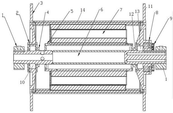
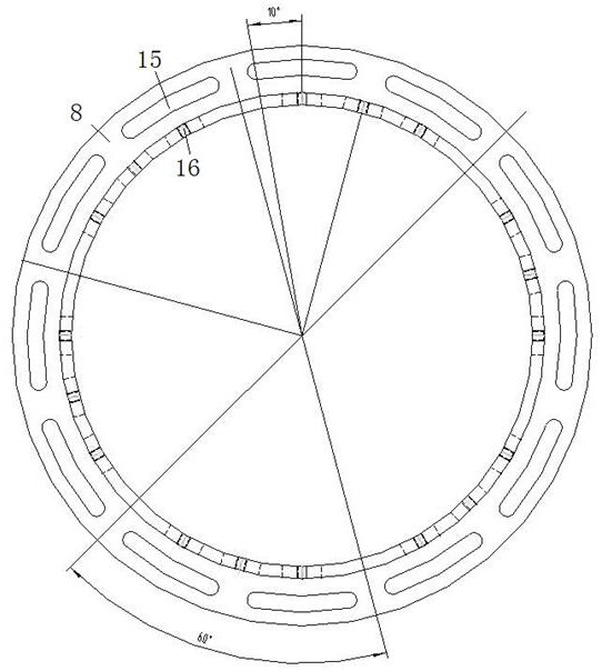
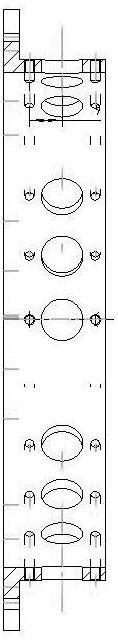
[0019] Such as figure 1 , figure 2 , image 3 with Figure 4 The shown outer rotor switch reluctance direct drive roller includes a shaft 6, a stator 5 arranged on the shaft 6, a rotor 7 arranged on the stator 5, a roller 14 arranged on the rotor 7, and a roller 14 arranged on the shaft 6 the first bearing 10, the second bearing 13 at both ends, and the first bearing inner cover 4, the second bearing inner cover 4, the second bearing inner cover 12, The first outer bearing cover 3 and the second outer bearing cover 11, wherein the two end faces of the roller 14 are fixedly connected with the first outer bearing cover 3 and the second outer bearing cover 11 respectively, and a group of shafts arranged at the two ends of the shaft 6 Seat 1, and the sensor seat 8 that is arranged on one end of the shaft 6 and installed in the second bearing outer cover 11, and the sensor 9 installed on the sensor seat 8, wherein the sensor 9 communicates with the remote control assembly in a ...

Embodiment 2

[0021] Such as figure 1 , figure 2 , image 3 with Figure 4 The shown outer rotor switch reluctance direct drive roller includes a shaft 6, a stator 5 arranged on the shaft 6, a rotor 7 arranged on the stator 5, a roller 14 arranged on the rotor 7, and a roller 14 arranged on the shaft 6 the first bearing 10, the second bearing 13 at both ends, and the first bearing inner cover 4, the second bearing inner cover 4, the second bearing inner cover 12, The first outer bearing cover 3 and the second outer bearing cover 11, wherein the two end faces of the roller 14 are fixedly connected with the first outer bearing cover 3 and the second outer bearing cover 11 respectively, and a group of shafts arranged at the two ends of the shaft 6 Seat 1, and the sensor seat 8 that is arranged on one end of the shaft 6 and installed in the second bearing outer cover 11, and the sensor 9 installed on the sensor seat 8, wherein the sensor 9 communicates with the remote control assembly in a ...

Embodiment 3

[0023] Such as figure 1 , figure 2 , image 3 with Figure 4 The shown outer rotor switch reluctance direct drive roller includes a shaft 6, a stator 5 arranged on the shaft 6, a rotor 7 arranged on the stator 5, a roller 14 arranged on the rotor 7, and a roller 14 arranged on the shaft 6 the first bearing 10, the second bearing 13 at both ends, and the first bearing inner cover 4, the second bearing inner cover 4, the second bearing inner cover 12, The first outer bearing cover 3 and the second outer bearing cover 11, wherein the two end faces of the roller 14 are fixedly connected with the first outer bearing cover 3 and the second outer bearing cover 11 respectively, and a group of shafts arranged at the two ends of the shaft 6 Seat 1, and the sensor seat 8 that is arranged on one end of the shaft 6 and installed in the second bearing outer cover 11, and the sensor 9 installed on the sensor seat 8, wherein the sensor 9 communicates with the remote control assembly in a ...


PUM


Abstract

The invention belongs to the technical field of roller motor application, and particularly discloses an outer rotor switch reluctance direct drive roller, which comprises a shaft, a stator, a rotor, aroller, a first bearing, a second bearing, a first bearing inner cover, a second bearing inner cover, a first bearing outer cover, a second bearing outer cover, a group of shaft seats, a sensor seatand a sensor. The outer rotor switch reluctance direct drive roller has the advantages that 1, low-speed direct drive is achieved, a speed reduction system is omitted, a transmission chain is simplified, and reliability is high; 2, the speed is low, the torque is large, start and stop are stable, and overload start can be realized; 3, a mechanical deceleration system is omitted, the structure is simple and compact, and the occupied space is small; 4, the use and maintenance are convenient, the operation is safe and reliable, demagnetization is avoided, and the service life is long; 5, full-vector control is realized, operation modes are diversified, and accurate control and adjustment characteristics are realized; 6, the roller has higher comprehensive efficiency, and is efficient and energy-saving; 7, during multi-machine operation, power balance can be realized; and 8, a motor runs as usual without being burnt due to lack of items.

Description

technical field [0001] The invention belongs to the technical field of drum motor applications, and in particular relates to an outer rotor switched reluctance direct drive drum, which is widely used in industries such as metallurgy, mining, papermaking, coal, steel, building materials, electric power, chemical industry, transportation, and road construction machinery. Background technique [0002] At present, the production of the machinery industry is showing a trend of rapid growth. The main purpose of the three-phase asynchronous drum motor is as the power source of the equipment to make the equipment run normally. The drum motor is widely used. The drum motor is widely used in various industries as the active roller, such as Coal and ash transportation in steel mills, water pump operation in power plants, etc. [0003] At present, the electric drum produced in our country can be divided into two categories, one is the ordinary electric drum with the motor inside the dru...

Claims


Application Information

Patent Timeline
Patent Type & Authority Applications(China)
IPC IPC(8): H02K19/02H02K11/20H02K7/14H02K5/16
CPCH02K19/02H02K11/20H02K7/14H02K5/16
Inventor 龙霄韩建国赵勇陶清陈云崔善超
Owner 江苏苏仪集团有限公司
Why Eureka
Try Eureka