
Dynamic balance weight angle positioning device suitable for nuclear power plant main pump motor

An angle positioning, nuclear power plant technology, applied in the direction of electromechanical devices, electric components, electrical components, etc., can solve the problem that the influence coefficient cannot correctly characterize the vibration characteristics of the main pump motor, affect the calculation of the influence coefficient of the dynamic balance of the main pump motor, and affect the dynamic balance. Adjust the effect and other issues to achieve the effect of maintaining the correctness of the calculation, the structure is simple, and the levelness adjustment is convenient

Pending Publication Date: 2021-04-30
JIANGSU NUCLEAR POWER CORP +1
View PDF0 Cites 0 Cited by
  • Summary
  • Abstract
  • Description
  • Claims
  • Application Information

AI Technical Summary

Problems solved by technology

[0005] 1) It is difficult to locate the actual angle of the aggravation. At present, the on-site calibration of the aggravation angle is only based on visual estimation, and there is a certain deviation from the theoretical calculation results, which affects the effect of dynamic balance adjustment;
[0006] 2) There is a deviation between the actual aggravated position and the theoretically calculated position, which affects the calculation of the subsequent main pump motor dynamic balance influence coefficient, and long-term error accumulation will cause the calculated influence coefficient to not correctly represent the vibration characteristics of the main pump motor;
[0007] 3) Due to the large visual error, one adjustment will be unsuccessful, which will affect the maintenance progress and increase additional economic costs. At the same time, multiple adjustments will also increase the stay time of personnel at the maintenance site and increase unnecessary radiation risks

Method used


Image

  • Dynamic balance weight angle positioning device suitable for nuclear power plant main pump motor
  • Dynamic balance weight angle positioning device suitable for nuclear power plant main pump motor
  • Dynamic balance weight angle positioning device suitable for nuclear power plant main pump motor

Examples


Embodiment Construction

[0035] The present invention will be further described below by means of the accompanying drawings and specific embodiments.

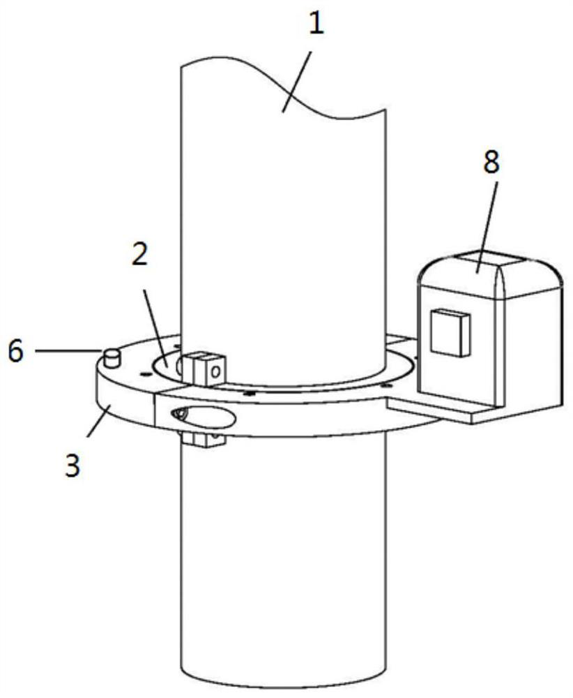
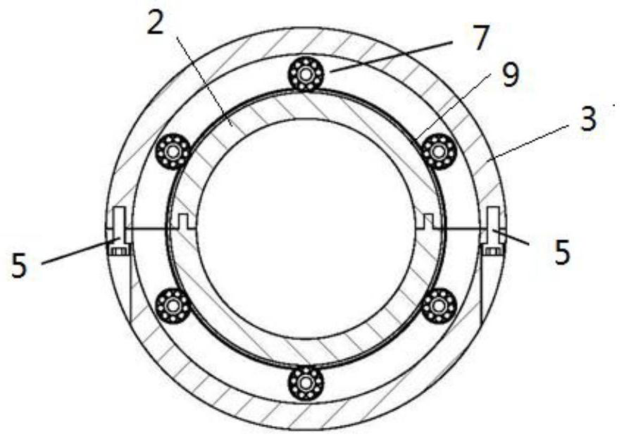
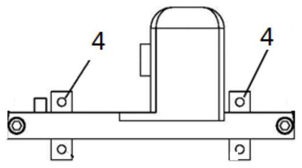
[0036] Such as figure 1 , figure 2 and image 3 As shown, the dynamic balance counterweight angle positioning device includes:

[0037] The locator inner ring 2 installed outside the motor lower shaft 1, the locator outer ring 3 installed outside the locator inner ring 2, the spirit level 6 installed on the locator outer ring 3, and the locator outer ring 3 installed And the laser ray meter 8 located on the outer edge.

[0038] The inner ring 2 of the above-mentioned locator is composed of two identical half rings, both of which enclose the lower rotating shaft 1 of the motor, and are fixed by the locking bolt 4 of the inner ring;

[0039] Similarly, the above-mentioned locator outer ring 3 is composed of two identical half-rings, both of which enclose the locator inner ring 2 and are fixed by the outer ring locking bolt 5;

[0040] Such as fig...


PUM


Abstract

The invention belongs to the nuclear power plant detection and maintenance technology, and particularly relates to a dynamic balance weight angle positioning device suitable for a main pump motor of a nuclear power plant; the device comprises a positioning instrument inner ring arranged outside a rotating shaft at the lower part of the motor, a positioning instrument outer ring arranged outside the positioning instrument inner ring, and a laser ray instrument arranged on the positioning instrument outer ring and positioned at the outer edge. Accurate and rapid positioning of the counterweight angle position is achieved, errors caused by visual estimation when the weighting angle is calibrated on site are eliminated, the weighting angle is kept consistent with a theoretical calculation result, the implementation effect of dynamic balance adjustment is guaranteed to the maximum extent, and dynamic balance adjustment succeeds at a time; and in addition, error accumulation of the actual weighted position can be avoided, and the calculation correctness of the dynamic balance influence coefficient of the subsequent main pump motor is kept, so that the vibration characteristic of the main pump motor can be correctly represented.

Description

technical field [0001] The invention belongs to the detection and maintenance technology of nuclear power plants, and in particular relates to a dynamic balance counterweight angle positioning device suitable for a main pump motor of a nuclear power plant. Background technique [0002] The main coolant pump in the primary circuit of a nuclear power plant is a vertical two-speed three-phase asynchronous squirrel-cage motor, and the motor and the main pump body are connected by a torsion bar coupling. Before and after the previous maintenance of the unit, the vibration state of the motor will change to a certain extent, and the vibration will be high. Therefore, after each inspection, according to the vibration of the main pump motor, it is necessary to carry out dynamic balance adjustment. [0003] During previous implementations of the dynamic balance of the main pump motor, due to the large diameter of the motor flywheel and the small diameter of the motor shaft, the dista...

Claims


Application Information

Patent Timeline
IPC IPC(8): H02K11/21
CPCH02K11/21
Inventor 朱军荀蔚刘文超卢仲轩秦贯洲周正平管玉峰魏建军胡巍鲍勇李震洪刘金剑
Owner JIANGSU NUCLEAR POWER CORP
Learn More