
1200-watt high-speed motor controller

A high-speed motor and controller technology, applied in the direction of closed casings, electrical components, casings/cabinets/drawer parts, etc., can solve the problems of poor terminal exhaust, product damage, and damage to PCB board electronic components, etc. question

Pending Publication Date: 2021-04-30
灏博电子科技(南京)有限公司
View PDF0 Cites 1 Cited by
  • Summary
  • Abstract
  • Description
  • Claims
  • Application Information

AI Technical Summary

Problems solved by technology

[0004] The technical problem to be solved by the present invention is to overcome that the welding surface of the copper terminal in the prior art does not have an exhaust groove, and the exhaust around the terminal is not smooth during welding, which causes the displacement of the copper terminal under the action of the gas, resulting in the overall assembly. The terminal holes of the terminal and the shell are not concentric, so that the connection contact area with the PCB board is relatively small. When the product is subjected to vibration, the amplitude of the PCB board will be large, which will easily cause the PCB board to break and be assembled. And the existing copper terminal The waterproof is simply put an O-ring on the copper terminal, but in fact it cannot meet the waterproof standard specified by the product. At the same time, the existing upper and lower PCB board connections are connected by hexagonal copper studs. Since the copper stud itself has a small contact area with the PCB, it cannot firmly connect the upper and lower PCB boards together, resulting in the product not being able to effectively resist the vibration generated in actual work and damaging the soldered parts on the PCB board. Electronic components, which will lead to product damage, functional failure and damage to the defects of components soldered on the PCB board, provide 1200 watts high-speed motor controller

Method used


Image

  • 1200-watt high-speed motor controller
  • 1200-watt high-speed motor controller
  • 1200-watt high-speed motor controller

Examples


Embodiment Construction

[0022] The preferred embodiments of the present invention will be described below in conjunction with the accompanying drawings. It should be understood that the preferred embodiments described here are only used to illustrate and explain the present invention, and are not intended to limit the present invention.

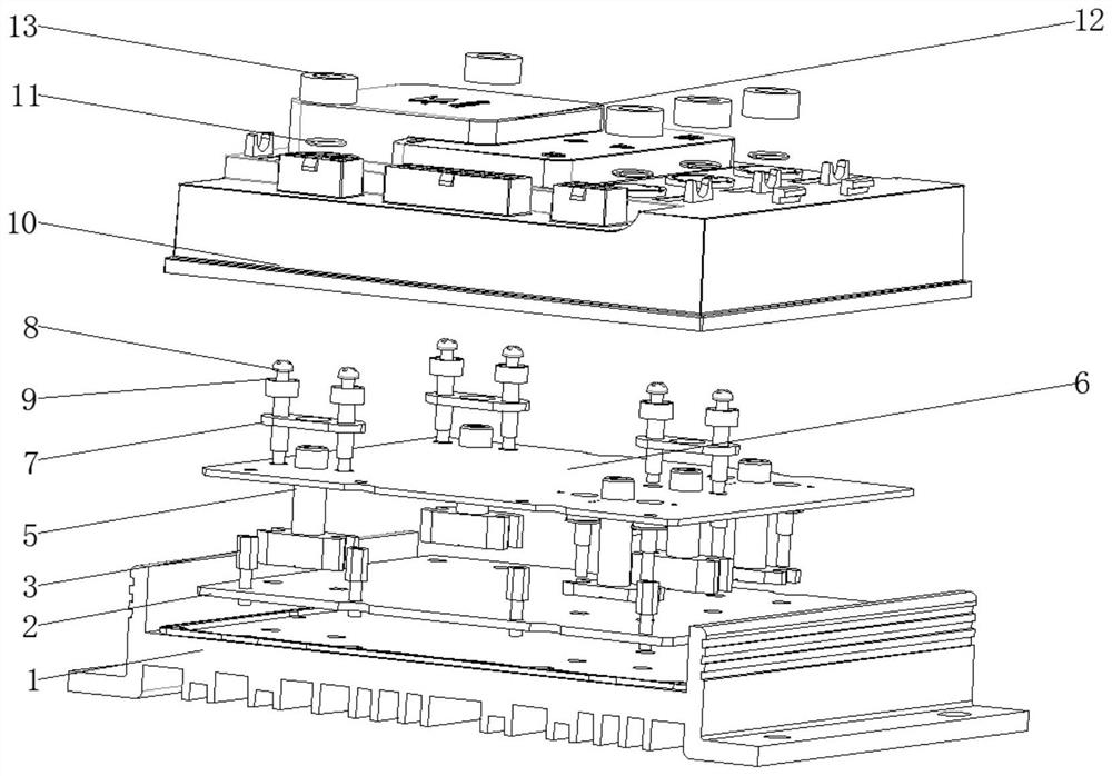
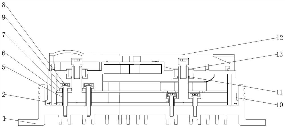
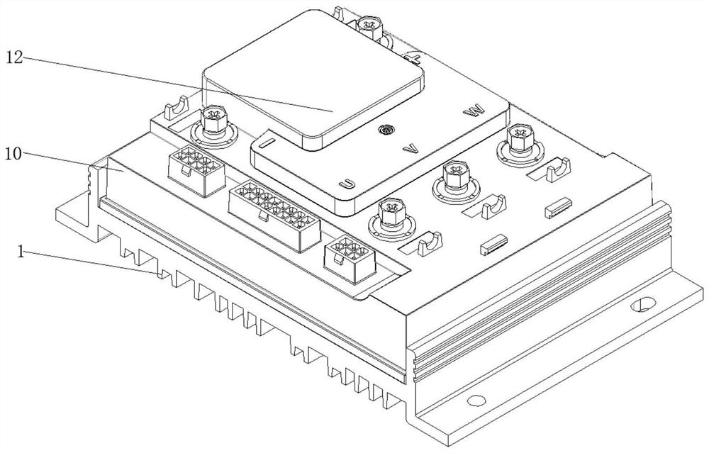
[0023] Such as figure 1 and figure 2 As shown, the 1200-watt high-speed motor controller includes a base 1 and an upper PCB board 6, and is characterized in that: a lower PCB board 2 is arranged above the base 1, and a positioning hexagonal stud 3 is threaded on the top of the lower PCB board 2, The horizontal line of the lower PCB board 2 is parallel to the horizontal line of the upper PCB board 6, and the lower surface of the lower PCB board 2 and the upper surface of the base 1 are closely attached, and the upper PCB board 6 and the lower PCB board 2 Keep parallel, so that when fixing the upper PCB board 2 and the lower PCB board 2, there will be no gap between...


PUM


Abstract

The invention discloses a 1200-watt high-speed motor controller which comprises a base and an upper PCB. A lower PCB is arranged above the base, a positioning hexagonal stud is in threaded connection with the upper portion of the lower PCB, and an exhaust groove is formed at the upper portion of the hexagonal stud; a copper terminal is arranged above the exhaust groove, a copper terminal pressing plate is arranged above the upper PCB, and the upper PCB is located above the copper terminal; the left side and the right side of the copper terminal pressing plate are in threaded connection with the copper terminal pressing plate fastening screws, and the lower portions of the copper terminal pressing plate fastening screws are sleeved with insulating sleeves. Compared with an existing common motor controller, the 1200-watt high-speed motor controller has the advantages that the copper terminals are not prone to displacement in the welding process, non-concentricity of the terminals and the terminal holes of a shell in the overall assembling process is avoided, the 1200-watt high-speed motor controller is sealed through a filling sealant, so that the waterproof grade of the controller is further improved, and meanwhile, breakage of the PCB due to generated vibration in the assembling or moving process is avoided.

Description

technical field [0001] The invention relates to a 1200-watt high-speed motor controller. Background technique [0002] Electric vehicles, that is, electric drive vehicles, also known as electric drive vehicles, electric vehicles are divided into AC electric vehicles and DC electric vehicles. Generally speaking, electric vehicles use batteries as energy sources, and convert electrical energy into mechanical energy through controllers, motors and other components. Vehicles that change the speed by controlling the current, at present, the terminals of the power line and phase line of electric vehicles are mainly combined terminals and discrete terminals. [0003] However, due to the problem of the design process structure, these terminals will be displaced when they are welded to the aluminum substrate, and the height of the top plane of the terminal and the plane of the aluminum substrate after welding also exceeds the design value; secondly, the current waterproof of this ter...

Claims


Application Information

Patent Timeline
IPC IPC(8): H05K5/00H05K5/02H05K5/06H05K7/14
CPCH05K5/0004H05K5/0213H05K5/064H05K7/1401
Inventor 胡鸿元席强
Owner 灏博电子科技(南京)有限公司
Learn More