
Eureka
For R&D, Eureka makes reading and utilizing patents & technical documents easy.
Eureka AIR
Designed for self-driven R&D workflows. Generate viable solutions, solve complex R&D challenges, empower your innovation with AI.

Eureka Materials
Designed for material experts only. Revolutionize your material R&D, from search, analyze, to developing new materials.

TechResearch
Generate reliable direction feasibility study reports for your R&D in just a few steps.

TechSeek
Discover and master advanced knowledge NOW. Basics, ideas, possibilities, all at once.

TechMind
As an expert in R&D Theories, TechMind can generates customized viable solutions instantly.

TechRisk
Analyze your overall solution with one click, know your potential R&D risks in advance.

TechMonitor
Get weekly tech updates, stay abreast of the latest tech innovations and key insights.
Straw biogas slurry uniform mixing device for environment-friendly biogas engineering
A uniform mixing and biogas technology, applied in the field of biogas slurry resource treatment, can solve the problems of uneven mixing, large uncorroded straw impurities, etc.
- Summary
- Abstract
- Description
- Claims
- Application Information
AI Technical Summary
Problems solved by technology
Method used
Image

Examples
Embodiment 1
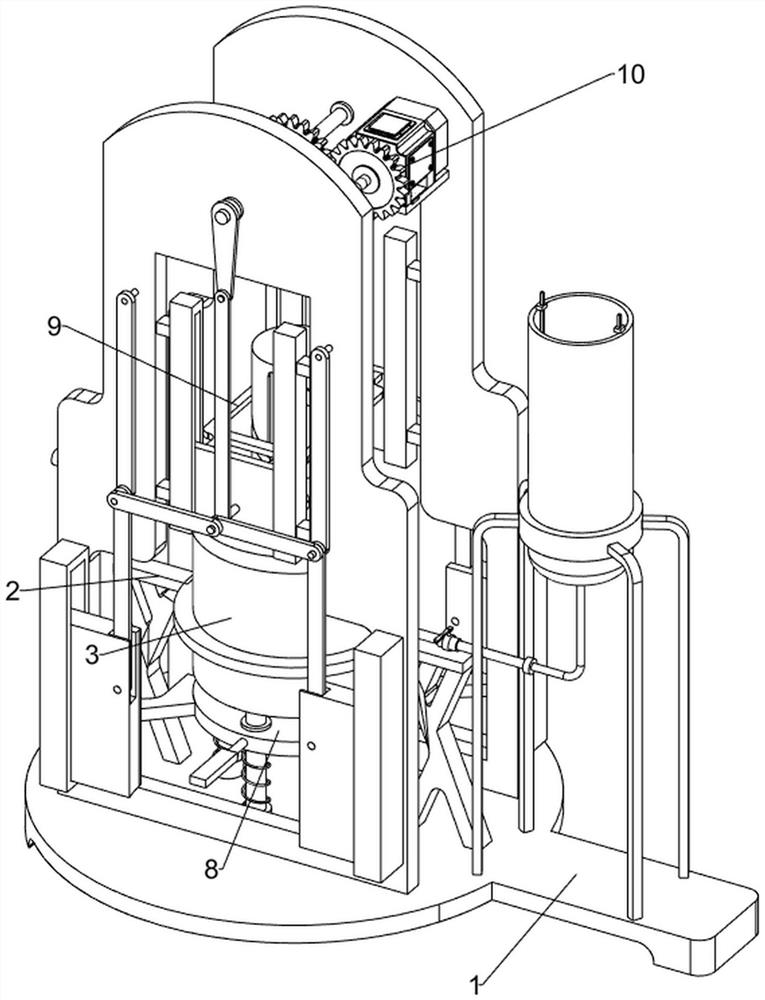
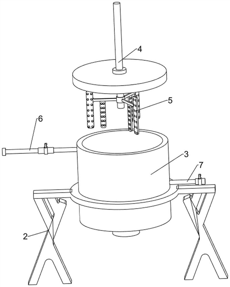
[0028] Such as figure 1 , figure 2 , image 3 , Figure 4 and Figure 5 As shown, a straw biogas slurry uniform mixing device for environmental protection biogas projects includes a base 1, a bracket 2, a mixing box 3, a rotating shaft 4, a stirring blade 5, a liquid inlet pipe 6, a liquid outlet pipe 7, a pushing mechanism 8, The rotating mechanism 9 and the driving mechanism 10, the top of the base 1 is symmetrically provided with a bracket 2, a mixing box 3 is arranged between the two brackets 2, the top center of the mixing box 3 is rotatably provided with a rotating shaft 4, and the lower side of the rotating shaft 4 is provided with a stirring blade 5 , the stirring blade 5 is located in the mixing box 3, the upper right side of the side wall of the mixing box 3 is connected with the liquid inlet pipe 6, the mixing box 3 is far away from the liquid inlet pipe 6, and the lower side of the left side of the side wall is provided with a liquid outlet pipe 7, and the top ...
Embodiment 2
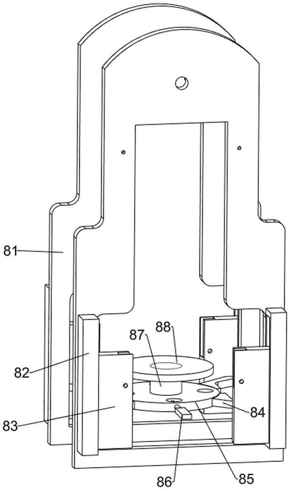
[0034] Such as Figure 6 and Figure 7 As shown, on the basis of Embodiment 1, it also includes a second connecting rod 11, a mounting shaft 12, a third connecting rod 13, a second fixed shaft 14 and a fourth connecting rod 15, and the two mounting plates 81 are far away from each other. The upper part of the side is symmetrically rotatably provided with a second connecting rod 11, the lower end of the second connecting rod 11 is provided with a mounting shaft 12, and the mounting shaft 12 is rotatably provided with a third connecting rod 13, and the two third connecting rods 13 on the same side The connecting rods 13 are all rotatably connected to the first fixed shaft 107 on the same side, and the first slider 83 is provided with a square groove at the opposite side wall, and the second fixed shaft 14 is arranged in the middle of the square groove of the first slider 83. The second fixed shaft 14 is rotatably provided with a fourth connecting rod 15, and the fourth connecti...
PUM
 Abstract
Description
Claims
Application Information
 - R&D Engineer
- R&D Manager
- IP Professional
- Industry Leading Data Capabilities
- Powerful AI technology
- Patent DNA Extraction
Browse by: Latest US Patents, China's latest patents, Technical Efficacy Thesaurus, Application Domain, Technology Topic, Popular Technical Reports.
© 2024 PatSnap. All rights reserved.Legal|Privacy policy|Modern Slavery Act Transparency Statement|Sitemap|About US| Contact US: help@patsnap.com