Iron plate stamping device capable of achieving automatic equidistant feeding

A punching device and equidistant technology, applied in the field of iron plate punching devices with distance feeding, can solve the problems of large workload, prone to deviation, low efficiency, etc., and achieve the effect of improving utilization rate, preventing dispersion and saving labor.

Pending Publication Date: 2021-05-04
雷天海
View PDF13 Cites 2 Cited by
  • Summary
  • Abstract
  • Description
  • Claims
  • Application Information

AI Technical Summary

Problems solved by technology

[0006] In order to overcome the shortcomings of workers who work for a long time and have a large workload, which requires a high degree of concentration, the stamping process is prone to deviations, resulting in waste of materials and low efficiency, the technical problem to be solved by the invention is to provide a method that reduces the workload of workers and improves Material utilization rate, iron plate stamping device with automatic equidistant feeding to improve work efficiency

Method used


Image

  • Iron plate stamping device capable of achieving automatic equidistant feeding
  • Iron plate stamping device capable of achieving automatic equidistant feeding
  • Iron plate stamping device capable of achieving automatic equidistant feeding

Examples


Embodiment 1

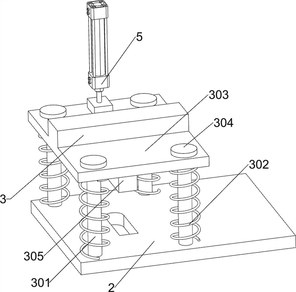
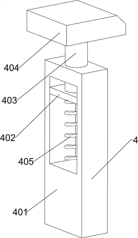
[0032]An automatic equidistant feed iron plate stamping device, such asFigure 1-4As shown, the base 1, the table 2, the stamping assembly 3, the one-way assembly 4, and the cylinder 5 are included, and the table 2 is mounted in the middle of the top of the base 1, and the stamping assembly 3 is mounted on the table 2, and the bottom left side of the base 1 is connected. There is a one-way assembly 4, and the cylinder 5 is mounted on the top of the base 1.

[0033]The stamping assembly 3 includes a first guide bar 301, a first spring 302, a first movable plate 303, a first baffle 304, and a punching block 305, and a first guide bar 301, a first guide bar 301. The sliding connection has a first movable plate 303, and the first movable plate 303 is located below the bump of the cylinder 5, and the first spring 302 is connected between the first movable plate 303 and the table 2, and the first spring 302 is set in the first guide. On the outer side of the rod 301, the first baffle 304 is c...

Embodiment 2

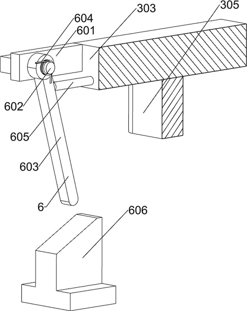
[0037]On the basis of Example 1, such asFigure 5 The moving assembly 6 is also included, and the moving assembly 6 includes a first support plate 601, a second support rod 602, a first contact rod 603, a torsion spring 604, a second contact rod 605, and a first contact block 606, The first support plate 601 is connected to the left side of the movable plate 303, and a second support rod 602 is connected between the first support plate 601, and the second support rod 602 is rotatably connected to the first contact rod 603, the first support plate. 601 is connected between the first contact rod 603, and the first movable plate 303 is connected to the left side of the first contact rod 603 in contact with the second contact rod 605, and the top of the base 1 is connected There is a first contact block 606, and the first contact block 606 is located below the first contact rod 603.

[0038]When the first movable plate 303 moves downward, the first support plate 601 moves downward with the ...

Embodiment 3

[0040]On the basis of Example 2, such asFigure 6 The collecting assembly 7 is also included, and the collecting assembly 7 includes a guide rail 701, a collection chamber 702, a second baffle 703, a connecting plate 704, a connecting rod 705, and a handle 706, a base 1 intermediate connection with a guide rail 701, guide rail 701 The collected box 702 is slidably connected, and the collecting box 702 is located below the punching block 305, and the rail 701 is connected to the back side of the guide rail 703, and the front side of the collecting box 702 is connected to the connecting plate 704, and the connecting plate 704 is connected to a connecting rod. 705, the connecting rod 705 is connected to the handle 706.

[0041]The material that is stamped will fall into the collecting box 702 at the through hole on the workbench 2, and after collecting the handle 706, the handle 706 pulls the collected frame out, the collection box slides on the guide rail 701, and the material within the ...


PUM


Abstract

The invention relates to an iron plate stamping device, in particular to an iron plate stamping device capable of achieving automatic equidistant feeding. The invention is to provide the iron plate stamping device capable of achieving automatic equidistant feeding, which reduces the workload of workers, increases the material utilization rate and improves the working efficiency. In order to realize the technical purpose, the invention provides the iron plate stamping device capable of achieving automatic equidistant feeding, which comprises a base, a stamping assembly, a one-way assembly and an air cylinder, wherein a workbench is installed in the middle of the top of the base, the stamping assembly is installed on the workbench, the one-way assembly is connected to the left side of the top of the base, and the air cylinder is installed on the rear side of the top of the base. According to the device, equidistant stamping of an iron plate can be completed through the stamping assembly and the one-way assembly, equidistant devices are additionally arranged on the basis of manual movement, operation by workers is facilitated, and the utilization rate of materials is increased.

Description

Technical field[0001]The present invention relates to a ferrule stamping device, and more particularly to an iron plate pressing device for an automatic equidistant feed.Background technique[0002]The iron board, the pronunciation is, Chinese words, means iron-made boards.[0003]Most of the iron plate cutting work is done by the workers. Workers put them on the protective gear, sit in the designated position, take the iron plate, place the iron plate at one end of the iron plate in the punch, start the press, the worker is on the punch When the timing is shifted, the iron plate is shifted, and the above action has been repeated until the iron plate does not have the position of the air, and the waste iron plate will be replaced with the new iron plate to continue the stamping. The above operation process workers are long. Time work work is high, requires spirituality to be highly concentrated, and the stamping process is prone to deviation, resulting in waste, and low efficiency.[0004...

Claims


Application Information

Patent Timeline
Patent Type & Authority Applications(China)
IPC IPC(8): B21D43/00B21D43/02B21D43/20B21D45/00B21D22/02
CPCB21D43/003B21D43/027B21D43/20B21D45/00B21D22/02
Inventor 雷天海
Owner 雷天海
Why Eureka
Try Eureka