Automobile exhaust emission purification device convenient to disassemble and assemble
A technology for purification devices and automobile exhaust, applied in exhaust devices, noise reduction devices, mechanical equipment, etc., can solve problems such as air pollution, lack of power, and exhaust pipes that cannot be exhausted in time
- Summary
- Abstract
- Description
- Claims
- Application Information
AI Technical Summary
Problems solved by technology
Method used
Image
Examples
Embodiment 1
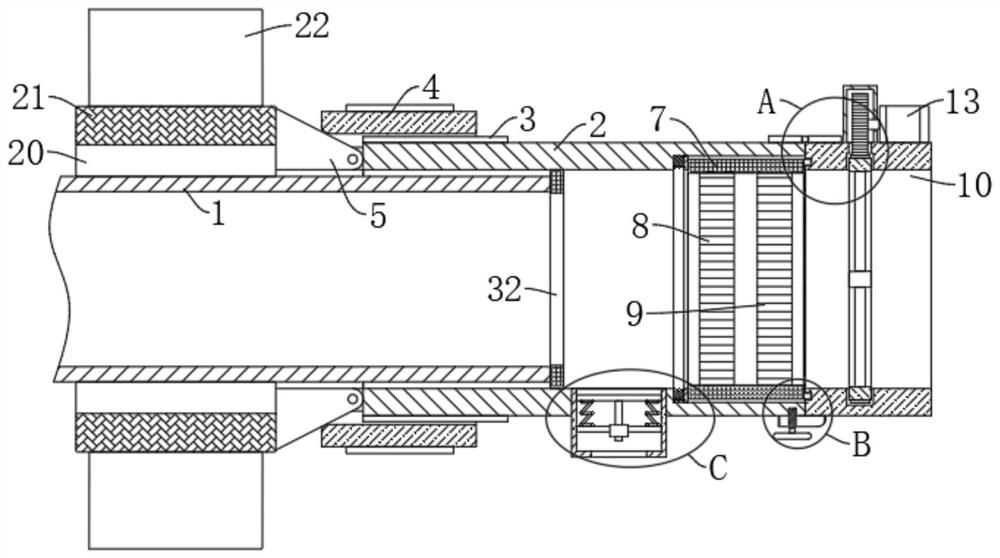
[0031] refer to Figure 1-5 , a vehicle exhaust emission purification device that is easy to disassemble and assemble, comprising an exhaust pipe 1 and a purification pipe 2. The purification pipe 2 is sleeved on the right end of the exhaust pipe 1. The outer wall is covered with a threaded sleeve 4, the left end of the purification pipe 2 is fixedly connected with a plurality of circumferentially distributed trapezoidal splints 5, the inner wall of the right end of the purification pipe 2 is provided with a placement groove 6, and an annular sleeve 7 is arranged in the placement groove 6. The first filter plate 8 and the second filter plate 9 are fixedly installed in the sleeve 7, and the right end of the purification pipe 2 is rotatably connected with an exhaust sleeve 10 matched with its left end, and the exhaust sleeve 10 and the purification pipe 2 are positioned through Mechanism connection, the exhaust sleeve 10 is equipped with a power-assisted exhaust device. When ins...
Embodiment 2
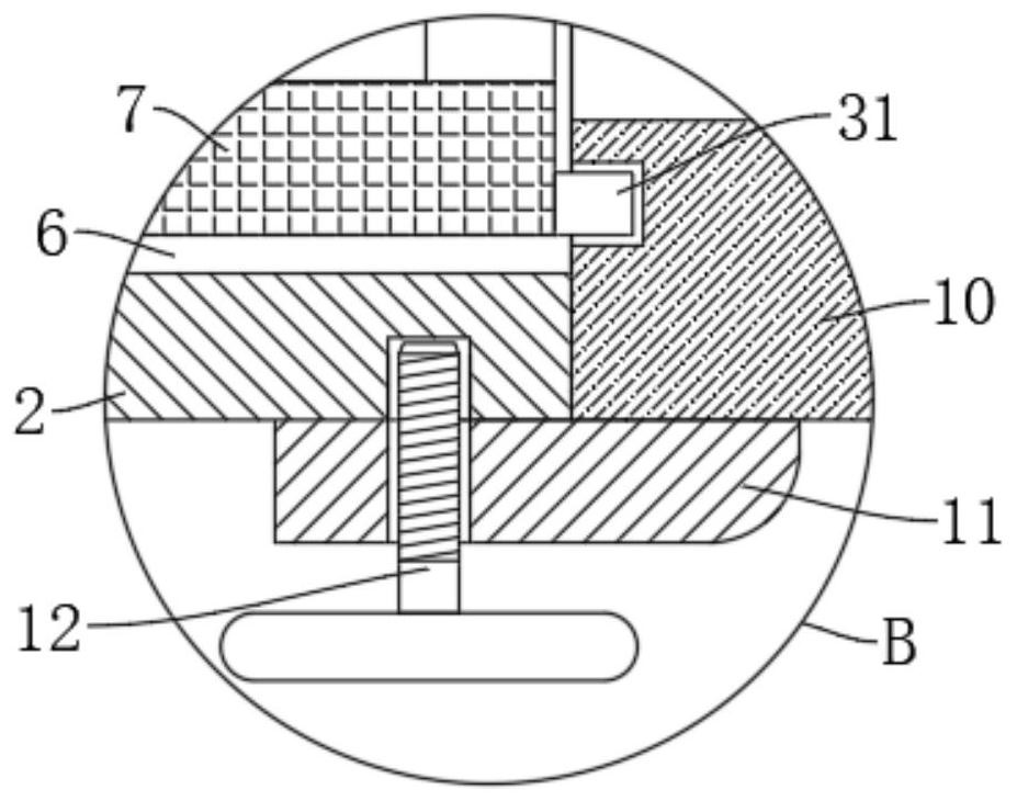
[0036] refer to figure 1 , image 3 , Figure 4 , is basically the same as Embodiment 1, furthermore: the positioning mechanism includes a positioning plate 11 fixedly connected to the side wall of the lower end of the exhaust sleeve 10, and the positioning plate 11 is fixedly connected to the purification pipe 2 by a screw 12, and the screw 12 There is a turning handle at the end. When the first filter plate 8 and the second filter plate 9 need to be disassembled, replaced and cleaned, unscrew the screw 12, and then rotate the exhaust sleeve 10 by turning the hinge 19 to open it. Take out the annular sleeve 7 from the placement groove 6 .
[0037]Furthermore, the left end of the placement groove 6 is elastically connected with an annular bottom plate 29 through a tightening spring 30, and the annular bottom plate 29 is against the side wall of the annular sleeve 7. When the exhaust sleeve 10 is opened, the annular bottom plate 29 is pressed tightly Under the action of the ...
Embodiment 3
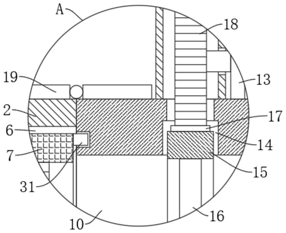
[0039] refer to figure 1 , figure 2 , which is basically the same as that of Embodiment 1, furthermore: the power-assisted exhaust mechanism includes an annular groove 14 arranged in the exhaust sleeve 10, and a circular ring 15 is rotatably connected in the annular groove 14, and the inner walls of the circular ring 15 are fixed A fan blade 16 is installed, a ring gear 17 is fixedly connected to the outer wall of the ring 15, a driving motor 13 is fixedly installed on the outer wall of the exhaust sleeve 10, and the output end of the driving motor 13 is fixedly connected to a driving gear meshing with the ring gear 17 18. The driving motor 13 drives the driving gear 18 to rotate, the driving gear 18 drives the ring gear 17 to rotate, the ring gear 17 drives the ring 15 and the fan blade 16 to rotate, and the fan blade 16 rotates to blow air to the outside of the exhaust sleeve 10, thereby realizing the purification pipe The role of the power-assisted exhaust of the exhaust ...
PUM
 Abstract
Description
Claims
Application Information
 - R&D
- Intellectual Property
- Life Sciences
- Materials
- Tech Scout
- Unparalleled Data Quality
- Higher Quality Content
- 60% Fewer Hallucinations
Browse by: Latest US Patents, China's latest patents, Technical Efficacy Thesaurus, Application Domain, Technology Topic, Popular Technical Reports.
© 2025 PatSnap. All rights reserved.Legal|Privacy policy|Modern Slavery Act Transparency Statement|Sitemap|About US| Contact US: help@patsnap.com


