
Miniature moving-magnetic series-connection two-stage linear compressor

A linear compressor and compressor technology, applied in the field of compressors, can solve the problems of large compression ratio and high exhaust temperature of compressors, and achieve the effects of lower exhaust temperature, enhanced reliability, and easy oil-free lubrication

Pending Publication Date: 2021-05-04
上海朗旦科技集团有限公司
View PDF0 Cites 0 Cited by
  • Summary
  • Abstract
  • Description
  • Claims
  • Application Information

AI Technical Summary

Problems solved by technology

[0005] In order to solve the above-mentioned problems of excessive compression ratio and high exhaust temperature of the compressor, reduce energy consumption and improve the efficiency of the compressor, the present invention provides a miniature moving magnet series two-stage linear compressor

Method used


Image

  • Miniature moving-magnetic series-connection two-stage linear compressor
  • Miniature moving-magnetic series-connection two-stage linear compressor
  • Miniature moving-magnetic series-connection two-stage linear compressor

Examples


Embodiment 1

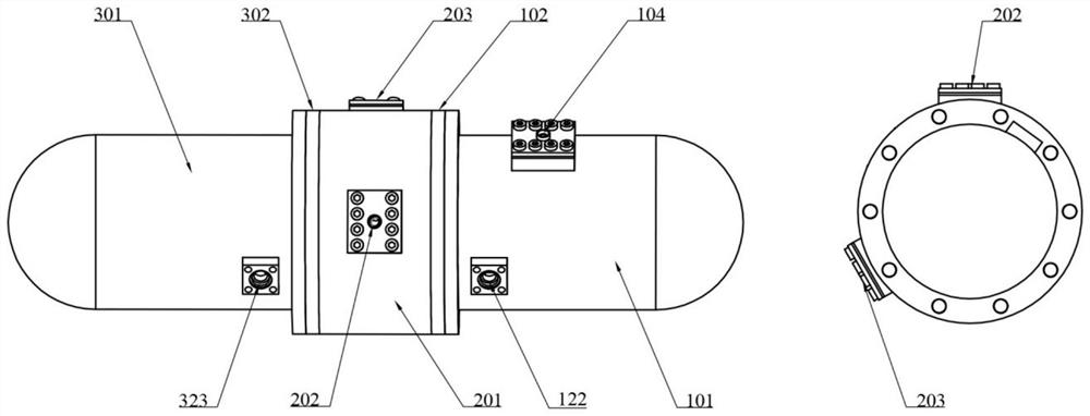
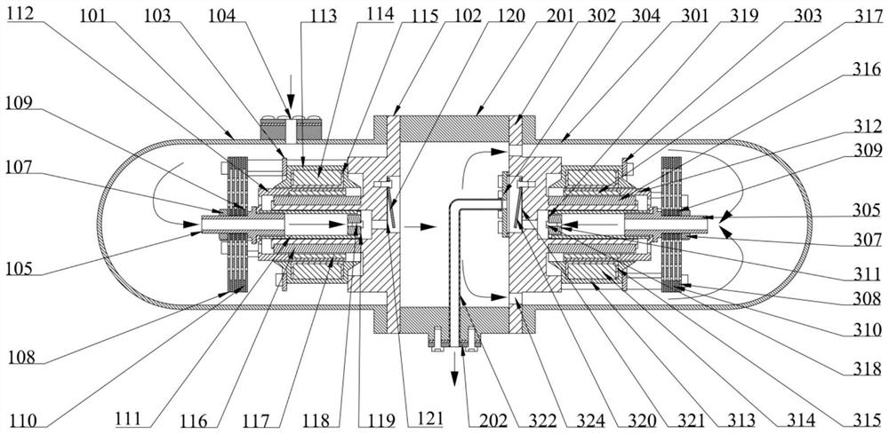
[0025] Such as figure 1 As shown, a miniature moving magnet series two-stage linear compressor includes a low-pressure stage compressor, an intermediate kit 201 and a high-pressure stage compressor. Both the high-pressure stage compressor and the low-pressure stage compressor include a shell, an integral frame, a dynamic subsections as well as linear motors.

[0026] A power interface 122 and a suction port 104 are arranged on the housing 101 of the low-pressure stage compressor.

[0027] The overall frame 102 of the low-pressure compressor has an exhaust hole, and a tongue-shaped reed exhaust valve 121 and a lift limiter 120 are installed. The exhaust valve 121 and the lift limiter 120 are fixed on the On the integral frame 102, the inner yoke 116 is glued on the integral frame.

[0028] The mover part of the low-pressure stage compressor includes a leaf spring 108, a small washer 109, a leaf spring washer 110, a connecting piece 105, a piston 111, a permanent magnet bracke...

Embodiment 2

[0044] Such as Figure 5 As shown, the structure of the high-pressure stage compressor and the low-pressure stage compressor in Embodiment 2 is the same as that of the compressor in Embodiment 1, and the operating principle is also the same, the difference is:

[0045] There is an air inlet 203 on the intermediate sleeve 201, through which the saturated refrigerant vapor from the intercooler enters the cavity of the intermediate sleeve 201, mixes with the refrigerant gas compressed and discharged by the low-pressure stage compressor, and is then compressed by the high-pressure stage. The circular air suction hole 324 on the overall frame of the machine enters the air suction cavity of the high-pressure stage compressor. When the pressure in the compression cavity of the high-pressure compressor is lower than the pressure in the suction cavity, the refrigerant gas enters the compression cavity through the suction channel in the high-pressure compressor connector 305 and the pis...


PUM


Abstract

The invention relates to a miniature moving-magnetic series-connection two-stage linear compressor which comprises a low-pressure-stage compressor, a middle kit and a high-pressure-stage compressor. The high-pressure-stage compressor and the low-pressure-stage compressor are oppositely arranged, are the same in structure and each comprise a shell, an overall rack, a linear motor and a rotor part. An air inlet is formed in the middle kit, saturated refrigerant steam coming out of a middle cooler enters a cavity of the middle kit through the air inlet, is mixed with refrigerant gas exhausted by the low-pressure-stage compressor in a compressed mode, and then enters an air suction cavity of the high-pressure-stage compressor through a round air suction hole in the overall rack of the high-pressure-stage compressor. When a high-pressure-stage compressor piston moves towards the compression cavity side, refrigerant gas is compressed, and two-stage compression is achieved. The low-pressure-stage linear compressor and the high-pressure-stage linear compressor are connected in series for operation, the pressure ratio and efficiency are improved, the exhaust temperature is reduced, and vibration and noise of the compressor are reduced.

Description

technical field [0001] The invention relates to a compressor, in particular to a miniature moving magnet series two-stage linear compressor. Background technique [0002] The compression refrigeration cycle is one of the main methods of refrigeration, and it is widely used in refrigerators and air-conditioning systems, so the compressor is compared to the heart of the air-conditioning system. The air conditioner compressor consumes a lot of electricity when it works. Compared with traditional reciprocating piston compressors, linear compressors have the characteristics of compact structure, small size, low energy consumption and high efficiency. Their applications have gradually shifted from aerospace and other military fields to civilian refrigeration equipment such as refrigerators and air conditioners. After the 1990s, foreign countries began to develop linear compressors for household refrigerators. Sunpower in the United States has the technology to develop linear comp...

Claims


Application Information

Patent Timeline
Patent Type & Authority Applications(China)
IPC IPC(8): F04B35/04F04B25/00F04B39/00F04B39/06F04B39/12H02K41/02H02K7/14
CPCF04B25/005F04B35/04F04B39/0005F04B39/0027F04B39/06F04B39/121H02K7/14H02K41/02
Inventor 刘政任道顺
Owner 上海朗旦科技集团有限公司
Learn More