
A Vacuum Suction Cup for Ultra-thin Optical Parts

A technology for optical parts and vacuum suction cups, applied in suction cups, connecting components, mechanical equipment, etc., can solve the problems of large deformation of the sucked object, large deformation of the vacuum suction cup, large space occupation, etc., to achieve high tensile strength, Space-saving, firm adsorption effect

Active Publication Date: 2022-03-18
FUDAN UNIV
View PDF14 Cites 0 Cited by
  • Summary
  • Abstract
  • Description
  • Claims
  • Application Information

AI Technical Summary

Problems solved by technology

Traditional vacuum suction cups can be divided into flexible vacuum suction cups and rigid vacuum suction cups according to their properties. Although flexible vacuum suction cups can fully fit the adsorbed objects when absorbing objects, the deformation of the vacuum suction cups is relatively large, resulting in the suction of objects. The deformation is also large, especially when the absorbed object is an ultra-thin part
Rigid vacuum suction cups are the opposite. Although the deformation of the vacuum suction cups is small, when absorbing rigid objects, there will be gaps between the bonding surfaces, and air leakage will occur, resulting in unreliable adsorption.
Moreover, the traditional vacuum suction cup is connected separately from the vacuum generator, which occupies a large space and has a complicated structure.

Method used


Image

  • A Vacuum Suction Cup for Ultra-thin Optical Parts
  • A Vacuum Suction Cup for Ultra-thin Optical Parts
  • A Vacuum Suction Cup for Ultra-thin Optical Parts

Examples


Embodiment Construction

[0016] In order to make the technical means and effects realized by the present invention easy to understand, the present invention will be described in detail below in conjunction with the embodiments and accompanying drawings.

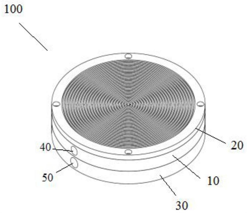
[0017] figure 1 It is a schematic diagram of the overall structure of a vacuum chuck for sucking ultra-thin optical parts in an embodiment of the present invention.

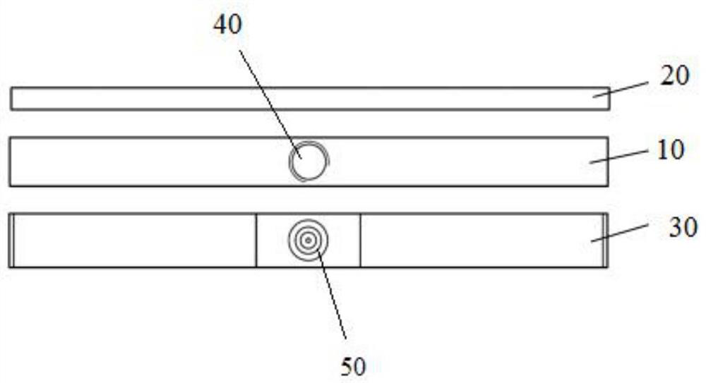
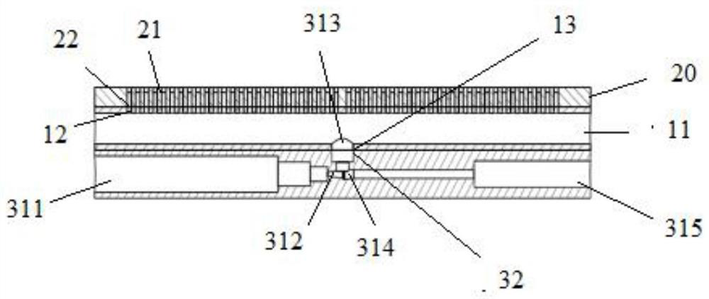
[0018] Such as figure 1 As shown, a vacuum chuck 100 for picking up ultra-thin optical components in this embodiment includes a vacuum passage portion 10 , a rubber suction portion 20 and a vacuum generator portion 30 .

[0019] The vacuum generator part 10, the rubber adsorption part 20 and the vacuum passage part 30 are sealed with a sealant, and screwed and fixed with screws and nuts to form an integrated structure.

[0020] The materials of the vacuum channel part 10 and the vacuum generator part 30 are both stainless steel, and the material of the rubber adsorption part 20 is iso...


PUM

PropertyMeasurementUnit
thicknessaaaaaaaaaa
diameteraaaaaaaaaa

Abstract

The invention provides a vacuum suction cup for absorbing ultra-thin optical parts, comprising: a vacuum passage part, which is disc-shaped, has a vacuum chamber arranged inside, and is arranged on the upper surface of the vacuum chamber through the center of the circle and uniformly arranged along the diameter direction The first through hole and the second through hole arranged in the center of the lower surface of the vacuum chamber; the rubber adsorption part is arranged above the vacuum passage part, which is disc-shaped, has an annular groove and is arranged below the annular groove with the The first through hole is aligned with the through hole; and the vacuum generator part is arranged under the vacuum passage part, which is disc-shaped, and the vacuum generator is arranged inside, and the center of the upper surface is provided with the second through hole. Aligned round holes, wherein the vacuum generator part, the rubber suction part and the vacuum passage part are sealed with sealant, and screwed and fixed with screws and nuts to form an integrated structure.

Description

technical field [0001] The invention relates to a vacuum chuck, in particular to a vacuum chuck for sucking ultra-thin optical parts. Background technique [0002] In today's increasingly developed industry, vacuum technology has been widely used in various industries and has achieved various important achievements. Traditional vacuum suction cups can be divided into flexible vacuum suction cups and rigid vacuum suction cups according to their properties. Although flexible vacuum suction cups can fully fit the adsorbed objects when absorbing objects, the deformation of the vacuum suction cups is relatively large, resulting in the suction of objects. The deformation is also large, especially when the picked-up object is an ultra-thin part. Rigid vacuum suction cups are the opposite. Although the deformation of the vacuum suction cup is small, when absorbing rigid objects, there will be gaps between the bonding surfaces, and air leakage will occur, resulting in unreliable ads...

Claims


Application Information

Patent Timeline
Patent Type & Authority Patents(China)
IPC IPC(8): F16B47/00
CPCF16B47/00
Inventor 王伟周冠宇徐敏
Owner FUDAN UNIV
Learn More