Check patentability & draft patents in minutes with Patsnap Eureka AI!

Vehicle positioning method based on image detection, and vehicle-mounted terminal

A vehicle positioning and image detection technology, which is applied in image analysis, image data processing, instruments, etc., can solve the problems that visual positioning cannot be performed, high-precision maps are difficult, and the effectiveness of visual positioning is low.

Pending Publication Date: 2021-05-04
BEIJING MOMENTA TECH CO LTD
View PDF5 Cites 2 Cited by
  • Summary
  • Abstract
  • Description
  • Claims
  • Application Information

AI Technical Summary

Problems solved by technology

However, when there are few landmarks or even no landmarks in the scene, it is difficult for the high-precision map to give enough effective information for visual positioning; or, when the landmarks cannot completely match the high-precision map due to occlusion or aging, the visual positioning may not be possible
All of the above lead to less effective visual localization

Method used


Image

  • Vehicle positioning method based on image detection, and vehicle-mounted terminal
  • Vehicle positioning method based on image detection, and vehicle-mounted terminal
  • Vehicle positioning method based on image detection, and vehicle-mounted terminal

Examples


Embodiment approach 1

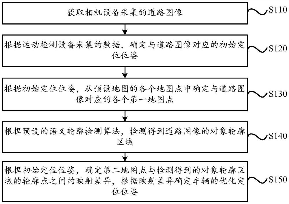
[0136] Embodiment 1: According to the value of the estimated pose, the transformation matrix between the world coordinate system and the camera coordinate system is determined; according to the transformation matrix and the projection relationship between the camera coordinate system and the image coordinate system, each first The map points are mapped to the image coordinate system to obtain the first mapping position of each first map point; the map points whose position difference between the first mapping position and the contour point in each first map point is less than the first preset threshold are taken as For a second map point on the contour of the object, a mapping difference between the first mapped position of the second map point and the contour point is determined.

[0137] When each object outline area is detected from the road image, and the category of each object outline area is also determined, according to the above-mentioned condition that the position di...

Embodiment approach 2

[0142] Embodiment 2: According to the value of the estimated pose, the transformation matrix between the world coordinate system and the camera coordinate system is determined; according to the transformation matrix and the projection relationship between the camera coordinate system and the image coordinate system, the detected contour points are Mapping to the world coordinate system to obtain the second mapping position of the contour point; the map point whose position difference between each first map point and the second mapping position of the contour point is less than the second preset threshold is regarded as being on the object contour A second map point of , determining a mapping difference between the second map point and a second mapped position of the contour point.

[0143] Wherein, the second preset threshold is a preset value, and the second preset threshold may be the same as or different from the first preset threshold.

[0144] To sum up, in this embodimen...


PUM


Abstract

The embodiment of the invention discloses a vehicle positioning method based on image detection, and a vehicle-mounted terminal. The method comprises the following steps: determining an initial positioning pose corresponding to a road image according to data collected by a motion detection device; determining each first map point corresponding to the road image from each map point of a preset map according to the initial positioning pose; detecting an object contour area of the road image according to a preset semantic contour detection algorithm; and according to the initial positioning pose, determining a mapping difference between the second map point and the detected contour point of the object contour area, and according to the mapping difference, determining an optimized positioning pose of the vehicle. The second map point is a map point on the object contour in each first map point, and each map point of the preset map is obtained by performing three-dimensional reconstruction on points in each object contour area in the sample road image in advance. By applying the scheme provided by the embodiment of the invention, the effectiveness of positioning the vehicle based on vision can be improved.

Description

technical field [0001] The present invention relates to the technical field of intelligent driving, in particular, to an image detection-based vehicle positioning method and a vehicle-mounted terminal. Background technique [0002] In the field of intelligent driving technology, vehicle positioning is an important part of intelligent driving. Usually, when the vehicle is driving, the vehicle pose can be determined according to the satellite positioning system. However, when the vehicle travels to a scene with weak or no satellite signal, in order to accurately determine the positioning pose of the vehicle, visual positioning can be used for positioning. [0003] Visual positioning is usually based on the matching between the semantic information of the road image collected by the camera device and the semantic information in the high-precision map. The semantic information in the high-precision map is modeled based on common landmarks on the road. Markers generally includ...

Claims


Application Information

Patent Timeline
Patent Type & Authority Applications(China)
IPC IPC(8): G06K9/00G06T7/73
CPCG06T7/73G06V20/588G06V20/582G06V20/584Y02T10/40
Inventor 李天威刘一龙徐抗童哲航
Owner BEIJING MOMENTA TECH CO LTD
Features
  • R&D
  • Intellectual Property
  • Life Sciences
  • Materials
  • Tech Scout
  • Unparalleled Data Quality
  • Higher Quality Content
  • 60% Fewer Hallucinations
Learn More