

Preparation method of groove type power device
A power device, trench technology, used in semiconductor/solid-state device manufacturing, semiconductor devices, electrical components, etc., can solve problems such as short circuit, device short circuit, affecting device reliability, etc., to avoid short circuit and improve reliability. Effect
- Summary
- Abstract
- Description
- Claims
- Application Information
AI Technical Summary
Problems solved by technology
Method used
Image

Examples
preparation example Construction
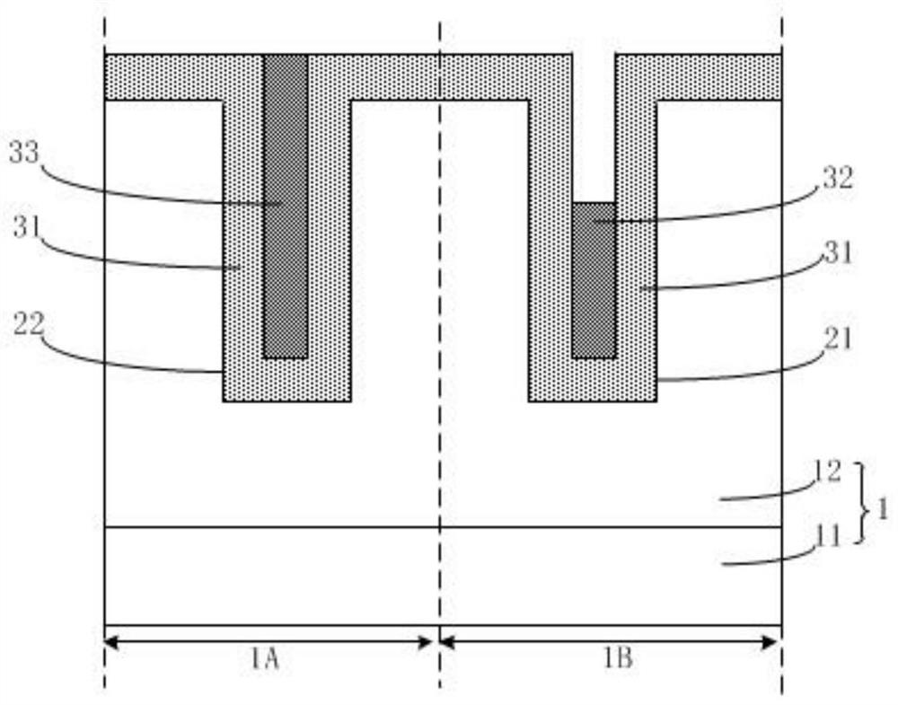
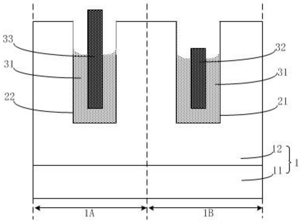
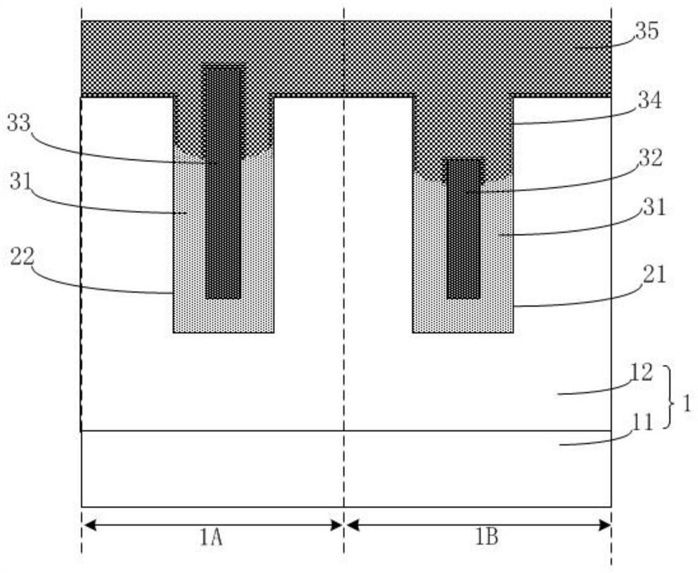
[0031] figure 2 A flow chart of the method for preparing a trench-type power device provided in this embodiment, Figure 3a-3e A schematic structural diagram of each step in the manufacturing method of the trench power device provided in this embodiment. This embodiment provides a preparation method of a trench power device to improve the reliability of the device, please refer to figure 2 ,include:
[0032] Step S1: providing a substrate, the substrate includes a device unit area and an electrode connection area, and an ONO layer is formed on the substrate;
[0033] Step S2: etching the substrate to form a plurality of first trenches in the device unit area and a plurality of second trenches in the electrode connection area;
[0034] Step S3: forming a first dielectric layer on the inner walls of the first trench and the second trench;
[0035] Step S4: Form a shielding gate layer and an electrode connection layer on the first dielectric layer in the first trench and th...
PUM
 Abstract
Description
Claims
Application Information