
Metamaterial slow wave structure unit based on Cherenkov radiation mechanism and slow wave structure

A slow-wave structure and metamaterial technology, applied in the cross field of metamaterial and microwave source technology, can solve the problem of low beam conversion efficiency, large volume, high power, high efficiency, uniform field distribution, and large space limit current and other problems, to achieve the effect of reducing the concentration of the structure's edge field, reducing the potential energy, and reducing the risk of breakdown

Active Publication Date: 2021-05-04
NAT UNIV OF DEFENSE TECH
View PDF6 Cites 2 Cited by
  • Summary
  • Abstract
  • Description
  • Claims
  • Application Information

AI Technical Summary

Problems solved by technology

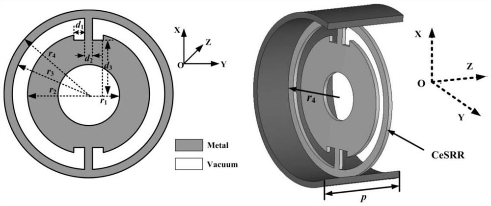
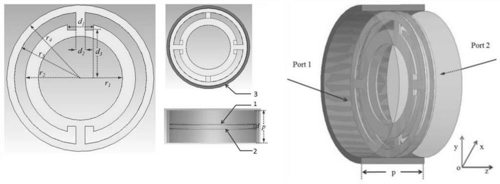
[0007] The technical problem to be solved by the present invention is to propose a metamaterial slow-wave structure unit based on the Cerenkov radiation mechanism and a metamaterial slow-wave structure composed of the unit, to overcome the traditional slow-wave structure with large volume and low beam conversion efficiency. Low problem; at the same time, it also overcomes the problem that the existing metamaterial slow wave structure cannot take into account high power, high efficiency, uniform field distribution, and large space limit current

Method used


Image

  • Metamaterial slow wave structure unit based on Cherenkov radiation mechanism and slow wave structure
  • Metamaterial slow wave structure unit based on Cherenkov radiation mechanism and slow wave structure
  • Metamaterial slow wave structure unit based on Cherenkov radiation mechanism and slow wave structure

Examples


Embodiment Construction

[0032] The accompanying drawings constituting a part of this application are used to provide further understanding of the present invention, and the schematic embodiments and descriptions of the present invention are used to explain the present invention, and do not constitute an improper limitation of the present invention.

[0033] figure 1 It is a structural schematic diagram of the L-band metamaterial slow-wave structure disclosed in the prior art 1 in the background introduction. The structure is composed of a metamaterial unit a, a metamaterial unit b, and a circular waveguide c. The metamaterial unit 1 is a circular ring with a fan-shaped opening and a fan-shaped protrusion. The fan-shaped opening and the fan-shaped protrusion are respectively located on both sides of the ring, and the opening angles are both α. The inner radius of the ring is rin, the outer radius is rout, the thickness is h, the inner radius of the circular waveguide is Win, and the metamaterial unit...


PUM


Abstract

The invention belongs to the crossing field of metamaterial and microwave source technology, and particularly relates to a Cherenkov-radiation-mechanism-based metamaterial slow wave structure unit and a metamaterial slow wave structure; the metamaterial slow wave structure unit comprise a hollow metal circular waveguide, a first metamaterial resonance unit and a second metamaterial resonance unit. The metamaterial slow wave structure unit has the following technical effects: the metamaterial slow wave structure unit can work under the cut-off frequency of the hollow circular waveguide with the same size, and has the advantage of miniaturization; high coupling impedance is achieved, and the effect beam wave interaction can be improved; the metamaterial slow wave structure unit has the advantage of uniform quasi TM01 mode field distribution, and the beam wave interaction efficiency can be improved through uniform field distribution; the electron beam can feel more conductor structures in the advancing process, the potential energy of the electron beam is reduced, and therefore the electron beam has larger kinetic energy, and the space limiting current is improved. The problem of structure edge field concentration caused by too thin thickness can be effectively solved, and the breakdown risk of the device is reduced; and meanwhile, a conductor part sensed by the electron beam is also added, so that the space limiting current can be improved.

Description

technical field [0001] The invention belongs to the intersecting field of metamaterial and microwave source technology, and specifically relates to a metamaterial slow-wave structural unit based on the Cerenkov radiation mechanism and a metamaterial slow-wave structure composed of the unit, which is beneficial to improving slow-wave The uniformity of the field distribution of the structure improves the beam-wave interaction efficiency and effectively reduces the volume of the microwave source. Background technique [0002] Metamaterial (Metamaterial, hereinafter referred to as MTM) is a macroscopic subwavelength composite material with an artificial, three-dimensional, and periodic cellular structure. It is designed to produce an optimized combination of properties that are not available in nature. Two or more reactions [Munk B. Metamaterials: Critique and Alternatives [M] / / Metamaterials: critique and alternatives. John Wiley, 2009.]. Metamaterials have attracted extensiv...

Claims


Application Information

Patent Timeline
IPC IPC(8): H01Q1/36H01Q15/00
CPCH01Q1/36H01Q15/0086
Inventor 贺军涛孔祥天令钧溥皮明瑶何宇放
Owner NAT UNIV OF DEFENSE TECH
Learn More