Supercharge Your Innovation With Domain-Expert AI Agents!

Power conversion device and electrical equipment

A power conversion device and circuit technology, which can be applied to conversion equipment without intermediate conversion to AC, high-efficiency power electronic conversion, and output power conversion devices, etc., can solve the problem of increasing the number and complexity of circuit components, and increasing the loss of drivers. , the increase of current harmonics and other problems, to reduce the switching loss and improve the efficiency of the drive.

Pending Publication Date: 2021-05-04
NIPPON DENSAN CORP
View PDF0 Cites 0 Cited by
  • Summary
  • Abstract
  • Description
  • Claims
  • Application Information

AI Technical Summary

Problems solved by technology

[0016] The inventors of the present application found that the first solution only improves the efficiency of the motor, but does not solve the problem of reducing the overall drive efficiency caused by the addition of a boost converter
Although the second solution can also improve AC motor efficiency, this solution increases the number and complexity of circuit components, and does not solve the problem of increased driver losses after adding a boost converter
Although the fourth solution and the fifth solution can reduce the switching loss, they can only reduce a small part of the switching loss, and will increase the current harmonics, which cannot effectively solve the overall driver efficiency reduction caused by the additional boost converter The problem

Method used


Image

  • Power conversion device and electrical equipment
  • Power conversion device and electrical equipment
  • Power conversion device and electrical equipment

Examples


Embodiment Construction

[0042] The foregoing and other features of the present application will become apparent from the following description, taken with reference to the accompanying drawings. In the specification and drawings, specific embodiments of the present application are specifically disclosed, which indicate some embodiments in which the principles of the present application can be adopted. It should be understood that the present application is not limited to the described embodiments, on the contrary, the present application The application includes all amendments, variations and equivalents that come within the scope of the appended claims.

[0043] In this embodiment of the application, the terms "first", "second", "upper", "lower", etc. are used to distinguish different elements from the title, but do not indicate the spatial arrangement or temporal order of these elements, etc. , these elements should not be limited by these terms. The term "and / or" includes any and all combinations...


PUM


Abstract

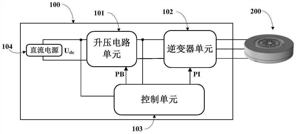
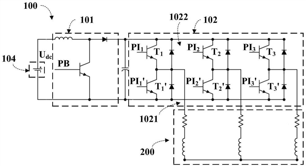
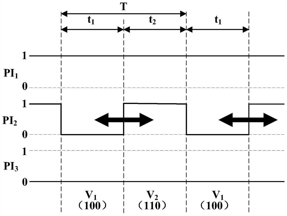
The embodiment of the invention provides a power conversion device and electrical equipment. The power conversion device supplies power to each phase of a three-phase motor, and comprises: a boost circuit unit connected to a DC power supply and used for boosting an input voltage input from a DC power supply according to a pulse width modulation boost signal; an inverter unit connected to the booster circuit unit and provided with a three-phase switching circuit comprising a plurality of switching elements and an output part, wherein the output part is connected to the three-phase switching circuit and supplies power to each phase of the three-phase motor; and a control unit used for outputting the pulse width modulation boosting signal to the boosting circuit unit, outputting a pulse width modulation switching signal to the inverter unit when detecting that the boosting circuit unit is in a boosting state, and controlling the switching elements of two phases in the three-phase switching circuit not to be switched on or switched off in a pulse width modulation period.

Description

technical field [0001] This application relates to the electromechanical field. Background technique [0002] In some DC / AC inverter application scenarios, the output voltage of the inverter needs to be higher than the input power voltage. Therefore, it is necessary to add a boost converter at the front end of the inverter to increase the DC BUS voltage of the inverter, thereby increasing the output voltage of the inverter. However, due to the increase of the boost converter, the circuit loss is inevitably increased, resulting in a decrease in the efficiency of the boost converter. [0003] The prior art proposes some solutions. [0004] The first solution is to use a traditional boost converter between the three-phase full-bridge rectifier and the smoothing capacitor to increase the voltage on the DC link of the smoothing capacitor, and then the three-phase full-bridge inverter modulates the output three-phase AC voltage to drive the motor , according to the working cond...

Claims


Application Information

Patent Timeline
IPC IPC(8): H02M7/48H02M3/00H02M3/10H02P27/00
CPCH02M7/48H02M3/00H02M3/10H02P27/00H02M7/5395H02M7/5387H02M7/53876H02M3/155H02M1/007H02M1/0048H02P2201/09H02P27/08H02M7/53871
Inventor 林明赞欧阳毅翔游欣璋
Owner NIPPON DENSAN CORP
Features
  • R&D
  • Intellectual Property
  • Life Sciences
  • Materials
  • Tech Scout
  • Unparalleled Data Quality
  • Higher Quality Content
  • 60% Fewer Hallucinations
Learn More