In-pipe spraying device suitable for bent pipe
A technology of internal spraying and pipe bending, applied in the direction of the spraying device, etc., can solve the problems of poor spraying effect, inability to spray, limited spraying distance, etc., and achieve uniform spraying effect
- Summary
- Abstract
- Description
- Claims
- Application Information
AI Technical Summary
Problems solved by technology
Method used
Image

Examples
specific Embodiment approach 1
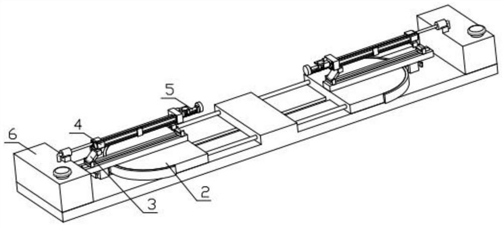
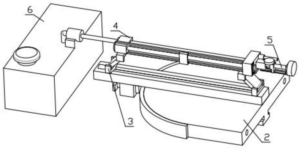
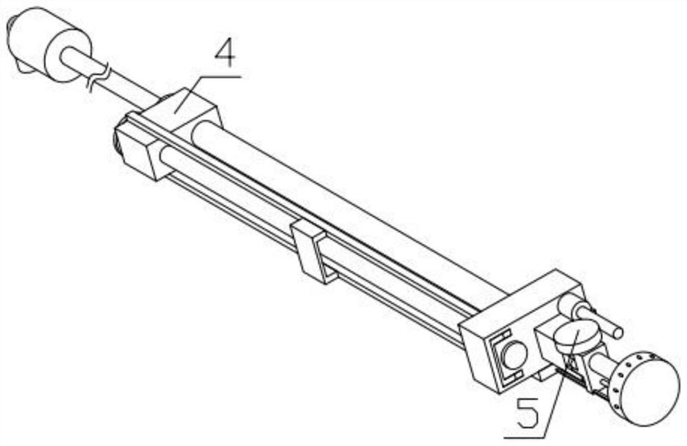
[0040] Combine below Figure 1-19 Describe this embodiment, an in-pipe spraying device suitable for elbows, including a distance adjustment mechanism 1, an angle adjustment mechanism 2, a height adjustment mechanism 3, a propulsion mechanism 4, an elbow mechanism 5 and a material box 6, the angle adjustment The mechanism 2 is threadedly connected with the spacing adjustment mechanism 1, the spacing adjustment mechanism 1 is fixedly equipped with a material box 6, the height adjustment mechanism 3 is rotatably installed on the angle adjustment mechanism 2, the propulsion mechanism 4 is fixedly installed on the height adjustment mechanism 3, and the elbow mechanism 5 It is fixedly installed on the propulsion mechanism 4, and the elbow mechanism 5 is fixedly connected with the material box 6.
specific Embodiment approach 2
[0042] Combine below Figure 1-19 Describe this embodiment, this embodiment will further explain the first embodiment, the distance adjustment mechanism 1 includes a bottom mounting plate 1-1, an internal motor 1-2, a main sprocket 1-3, an internal chain 1-4, a chain The wheel ring 1-5, the two-way threaded rod 1-6, the internal motor 1-2 is fixedly installed in the groove provided on the bottom mounting plate 1-1, and the main sprocket 1-3 is fixedly installed on the output of the internal motor 1-2 end, the main sprocket 1-3 meshes with the inner chain 1-4, the inner chain 1-4 meshes with the sprocket ring 1-5, the sprocket ring 1-5 is fixedly installed on the two-way threaded rod 1-6, and the chain The wheel ring 1-5 is rotatably installed in the groove provided on the bottom mounting plate 1-1, and the two ends of the bottom mounting plate 1-1 are respectively fixedly equipped with material boxes 6.
specific Embodiment approach 3
[0044] Combine below Figure 1-19 Describe this embodiment, this embodiment will further explain the second embodiment, the angle adjustment mechanism 2 includes a main sliding plate 2-1, a semi-circular toothed part 2-2, a toothed insert 2-3, and a fixed housing 2 -4, the internal spring 2-5, the main sliding plate 2-1 is slidably installed in the groove provided on the bottom mounting plate 1-1, and the semi-annular toothed part 2-2 is fixedly installed on the main sliding plate 2-1, The main sliding plate 2-1 is threadedly connected with the two-way threaded rod 1-6, the toothed insert 2-3 is inserted into the tooth groove of the semi-circular toothed part 2-2, and the inner spring 2-3 is fixedly installed on the toothed insert 2-3. 5. The other end of the internal spring 2-5 is fixedly installed in the groove of the fixed shell 2-4, the toothed insert 2-3 is slidably installed in the groove set on the fixed shell 2-4, and the fixed shell 2-4 is fixed Installed on the heig...
PUM
 Abstract
Description
Claims
Application Information
 - R&D
- Intellectual Property
- Life Sciences
- Materials
- Tech Scout
- Unparalleled Data Quality
- Higher Quality Content
- 60% Fewer Hallucinations
Browse by: Latest US Patents, China's latest patents, Technical Efficacy Thesaurus, Application Domain, Technology Topic, Popular Technical Reports.
© 2025 PatSnap. All rights reserved.Legal|Privacy policy|Modern Slavery Act Transparency Statement|Sitemap|About US| Contact US: help@patsnap.com