
Industrial wastewater treatment device with self-cleaning function

A technology of industrial waste water and treatment equipment, applied in the field of sewage treatment, can solve problems such as poor use effect, influence on filtration effect, accumulation of impurities, etc., and achieve the effect of improving use effect and simple and convenient dosing process

Inactive Publication Date: 2021-05-07
陈俊安
View PDF0 Cites 1 Cited by
  • Summary
  • Abstract
  • Description
  • Claims
  • Application Information

AI Technical Summary

Problems solved by technology

[0004] 1. After filtering, there will be a large amount of impurities accumulated in the filter cloth, which needs to be cleaned manually, which is time-consuming and laborious;
[0005] 2. After the impurities are cleaned, there will still be some impurities attached to the filter cloth, which will affect the subsequent filtering effect;
[0006] 3. Manual dosing is required during neutralization, and the use effect is poor

Method used


Image

  • Industrial wastewater treatment device with self-cleaning function
  • Industrial wastewater treatment device with self-cleaning function
  • Industrial wastewater treatment device with self-cleaning function

Examples


Embodiment 1

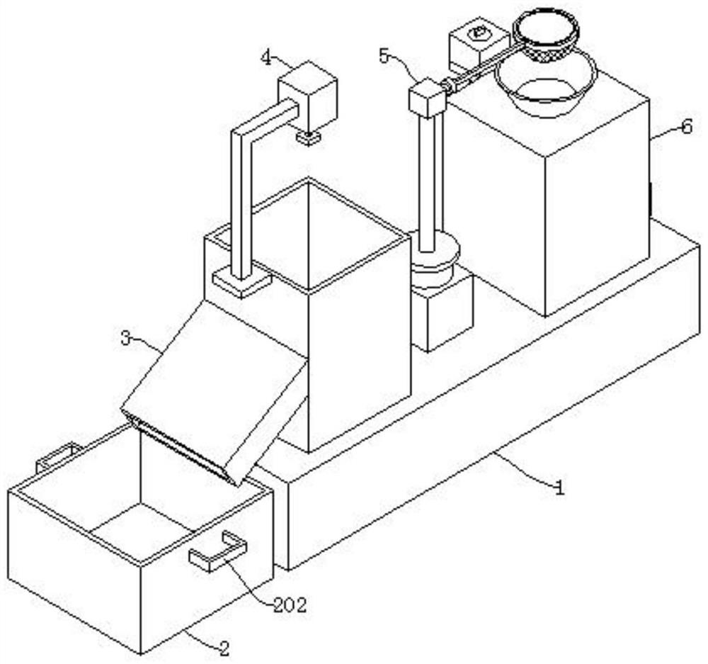
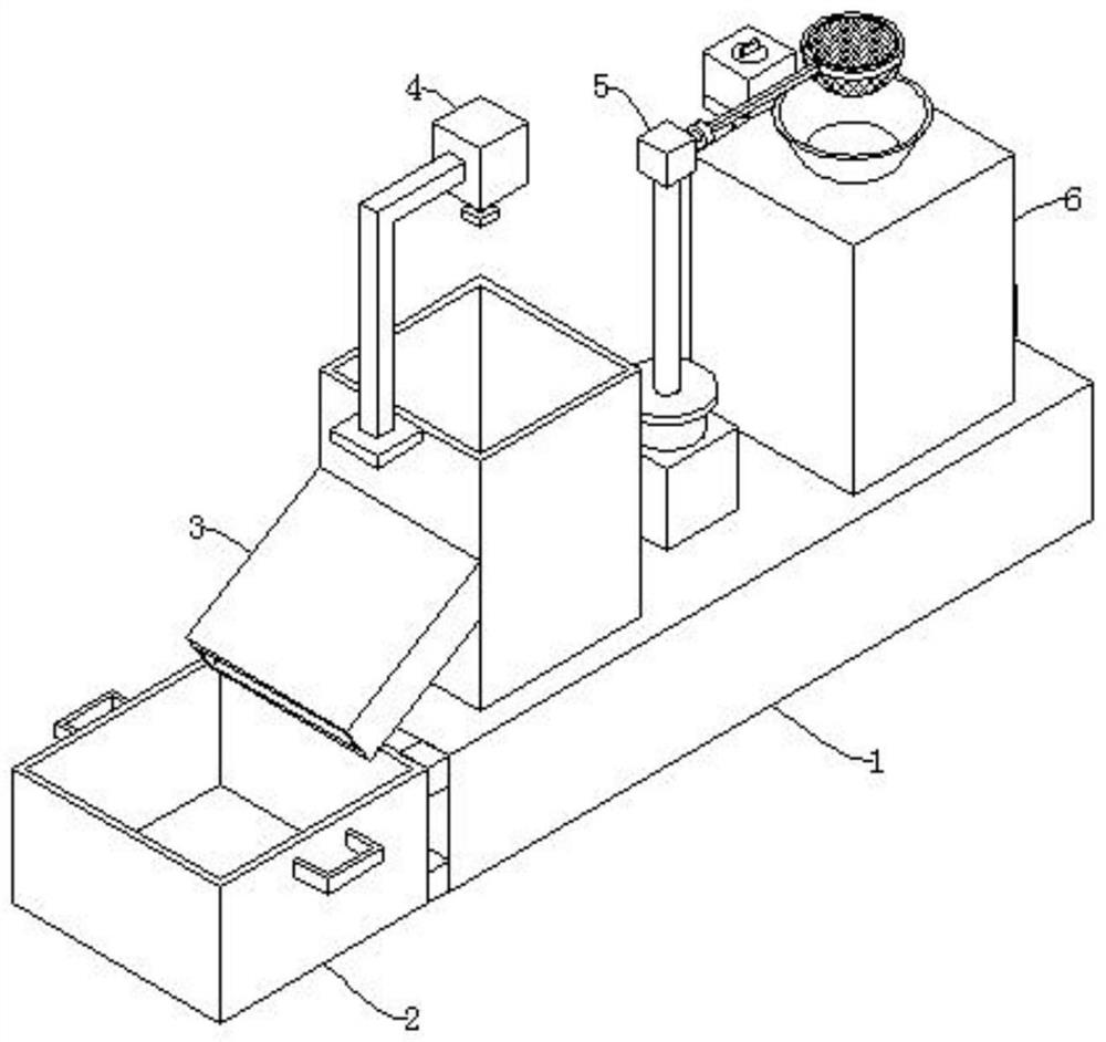
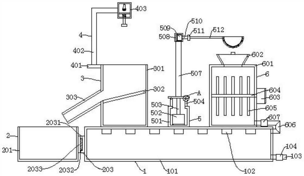
[0041] Such as figure 1 , image 3 , Figure 5 , Figure 6 , Figure 7 , Figure 8 As shown, an industrial wastewater treatment device with self-cleaning function includes a disinfection mechanism 1, a collection mechanism 2 for collecting impurities, and a conveying mechanism 3. The collection mechanism 2 is installed on the side of the disinfection mechanism 1, and the conveying mechanism is installed above the disinfection mechanism 1. The mechanism 3 also includes a knocking mechanism 4, a filtering mechanism 5, and a neutralizing mechanism 6. The knocking mechanism 4 is fixed on the conveying mechanism 3, the filtering mechanism 5 is arranged on one side of the conveying mechanism 3, and the neutralizing mechanism 6 is arranged on the filtering mechanism 5 A side away from the conveying mechanism 3;

[0042] The knocking mechanism 4 comprises a first fixed plate 401, a bent bar 402, a first protective box 403, a lifting plate 404, a first motor 405, a first rotating ...

Embodiment 2

[0048] Such as figure 2 , Figure 4 , Figure 5 , Figure 6 , Figure 7 , Figure 8 As shown, the difference between Embodiment 2 and Embodiment 1 is that the installation seat 2031, the first electromagnet 2032, and the adsorption plate 2033 are replaced by the insertion sleeve 2034, the second electromagnet 2035, and the insertion rod 2036, and it is necessary to move the collection box 201 , so that the second electromagnet 2035 is powered off, and the insertion rod 2036 is moved out of the insertion sleeve 2034 to move the collection box 201 .


PUM


Abstract

The invention discloses an industrial wastewater treatment device with a self-cleaning function, which comprises a disinfection mechanism, a collecting mechanism for collecting impurities, a conveying mechanism, a knocking mechanism, a filtering mechanism and a neutralizing mechanism, the collecting mechanism is arranged on the side surface of the disinfection mechanism, the conveying mechanism is arranged above the disinfection mechanism, the knocking mechanism is fixed on the conveying mechanism, the filtering mechanism is arranged on one side of the conveying mechanism, and the neutralizing mechanism is arranged on one side, far away from the conveying mechanism, of the filtering mechanism. By arranging the filtering mechanism, when impurities in filter cloth need to be cleaned, a second motor drives a rotating disc to rotate through a second rotating shaft, the rotating disc drives filter cloth to rotate by 180 degrees, a third motor drives a connecting disc to rotate through a third rotating shaft, the connecting disc drives the filter cloth to turn over by 180 degrees, impurities in the filter cloth enter a conveying box under the action of gravity, the impurities can be automatically cleaned, and time and labor are saved.

Description

technical field [0001] The invention relates to the technical field of sewage treatment, in particular to an industrial waste water treatment device with self-cleaning function. Background technique [0002] Industrial wastewater includes production wastewater, production sewage and cooling water. It refers to wastewater and waste liquid produced in the process of industrial production, which contains industrial production materials, intermediate products, by-products and pollutants produced in the production process lost with water. There are many types of industrial wastewater with complex components. Since industrial wastewater often contains a variety of toxic substances, polluting the environment is very harmful to human health. Therefore, it is necessary to develop comprehensive utilization, turn harm into benefit, and take corresponding purification measures for disposal according to the pollutant composition and concentration in the wastewater. can be discharged. ...

Claims


Application Information

Patent Timeline
Patent Type & Authority Applications(China)
IPC IPC(8): C02F9/08
CPCC02F1/001C02F1/325C02F1/66C02F9/00C02F2201/002C02F2201/004C02F2201/005C02F2301/08C02F2303/04C02F2303/14C02F2303/16
Inventor 陈俊安王博扬
Owner 陈俊安
Learn More